Disk clamp apparatus

a technology of clamping apparatus and disk, which is applied in the field of clamping apparatus, can solve the problems of reducing the accuracy of recording, difficulty in keeping the surface accuracy of an edge part of the circumference of the center hole of the disk, and affecting the accuracy of recording

Inactive Publication Date: 2005-03-15
TEAC CORP
View PDF9 Cites 42 Cited by
  • Summary
  • Abstract
  • Description
  • Claims
  • Application Information

AI Technical Summary

Benefits of technology

Accordingly, it is a general object of the present invention to provide a novel and useful disk clamp apparatus where one or more of the problems described above are eliminated.
According to the above invention, it is possible to provide a disk clamp apparatus whereby the disk is clamped without being warped, and thereby it is possible to improve a record accuracy.
According to the above invention, it is possible to keep a surface accuracy of an edge part of a circumference of a center hole of the disk by narrowing an interval between a plurality of clamp forces applied to the edge part of the circumference of the center hole of the disk.
According to the present invention, it is possible to achieve a balance between a clamp force by a clamp member and a pressing force by a core adjusting member. As a result of this, it is possible to adjust a core of the disk to a center for rotating of the disk and clamp the disk stably and smoothly.

Problems solved by technology

Therefore, it is difficult to keep a surface accuracy of an edge part of a circumference of the center hole of the disk 8.
As a result, a problem to reduced record accuracy occurs.
Thus, if the record surface of the disk 8 is warped by even a small amount, an error may occur when recording is implemented by irradialting with a laser with an optical pick up.
Therefore, if the disk is clamped by the conventional disk clamp apparatus in a state where the inner circumference side of the disk is deformed downward and the outer circumference side of the disk is deformed upward, a problem may occur in that the accuracy of the recorded informetion is reduced.

Method used


Image

  • Disk clamp apparatus
  • Disk clamp apparatus
  • Disk clamp apparatus

Examples


first embodiment

FIG. 3 is an exploded perspective view showing a disk device to which a disk clamp apparatus according to the present invention is applied.

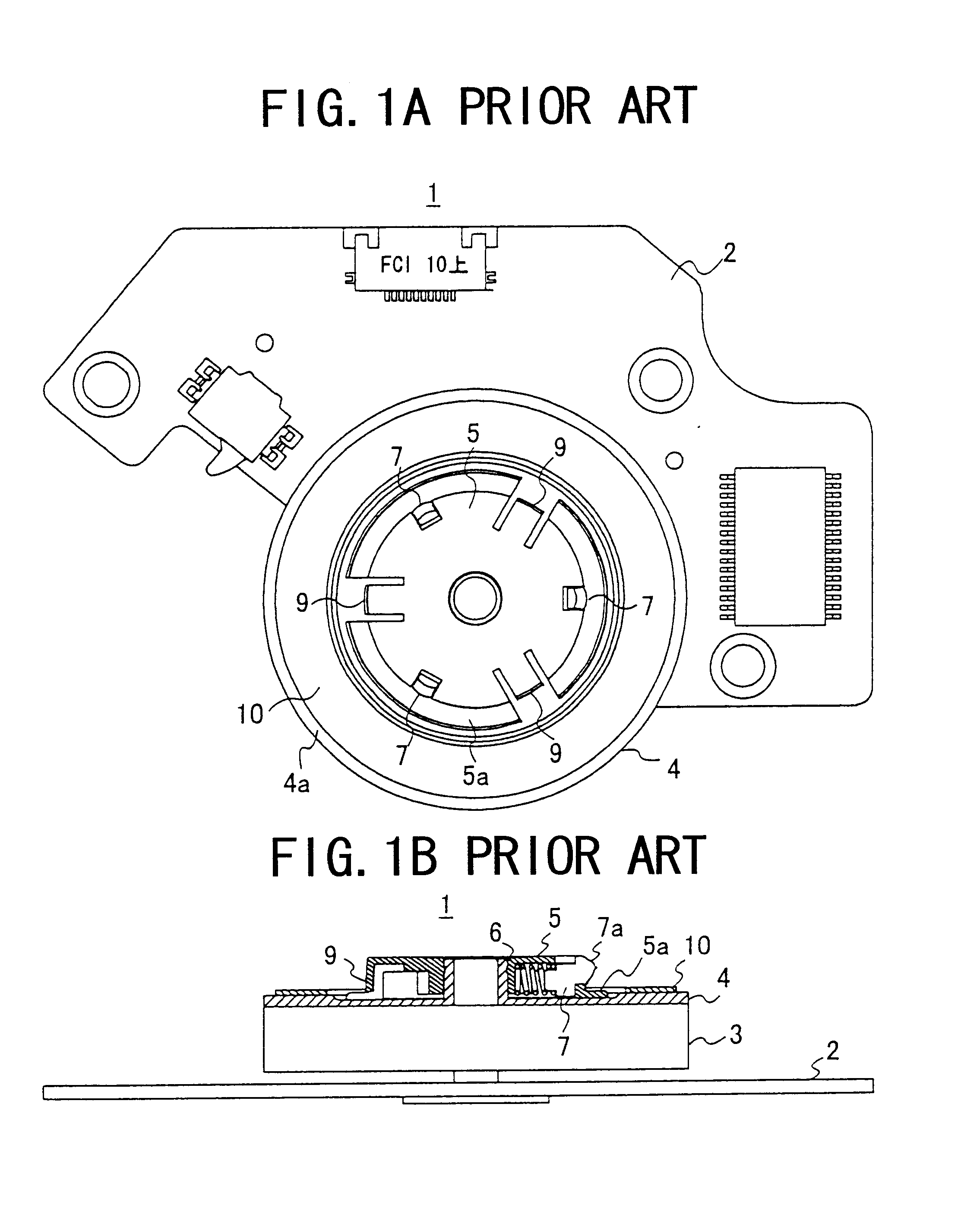
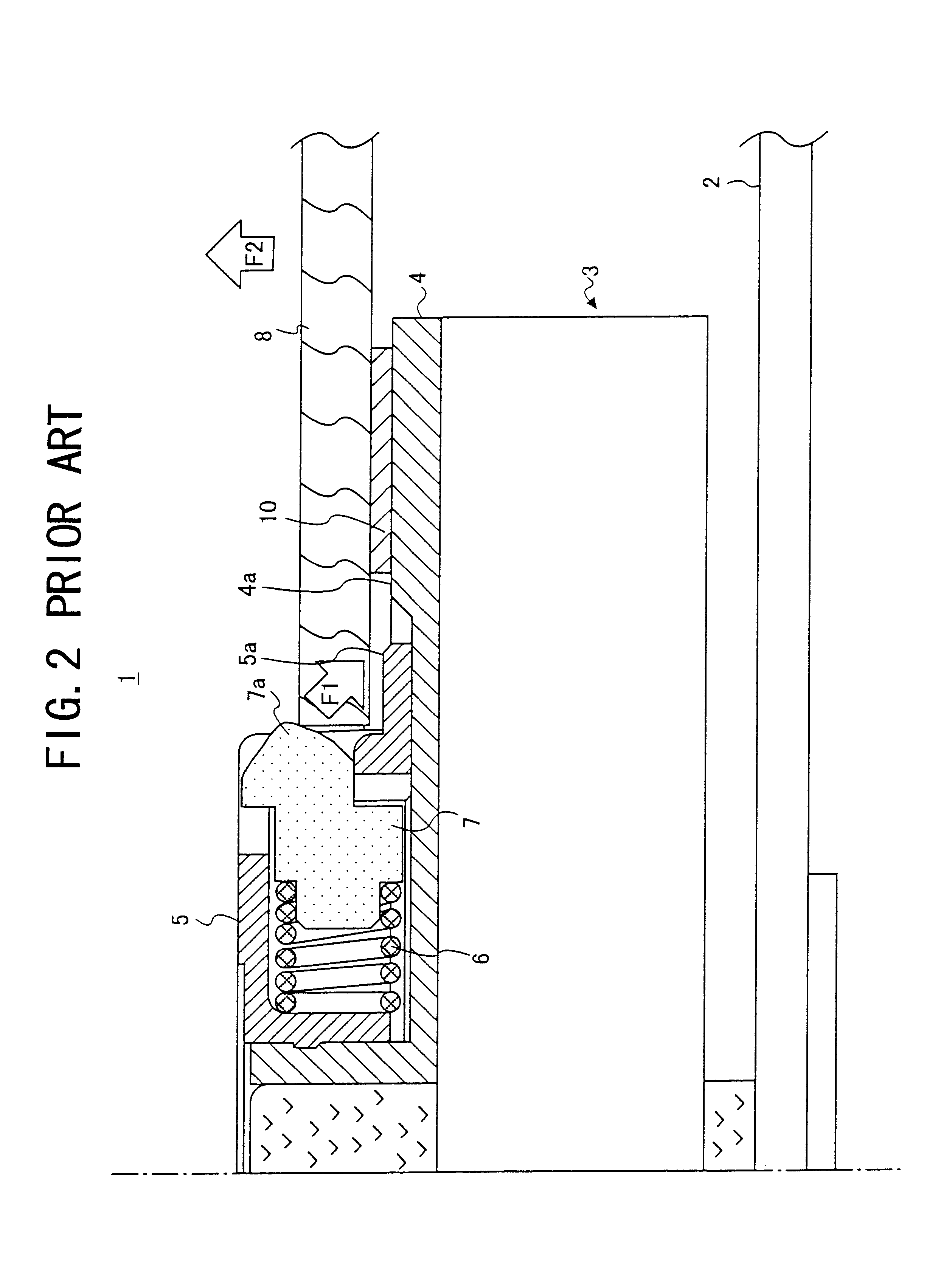
Referring to FIG. 3, a disk device 11, for instance a CD-ROM drive device, includes a tray 20 supporting a clamp table 18 in a state where the clamp table 18 can be rotated in a space formed between an upper cover 12 and a lower cover 16. A disk clamp apparatus 23 is provided at a center of a clamp table 18. A disk 22 shown as a one doted line in FIG. 3 has an inner circumference clamped by the disk clamp apparatus 23. A disk storage part 24 having a diameter greater than a diameter of the disk 22 is formed around the clamp table 18.

An optical pick up 26 is provided below the disk storage part 24 as the optical pick up 26 can move in a disk radial direction. Information which is recorded in the disk 22 clamped by the disk clamp apparatus 23 of the clamp table 18 is read out by the optical pick up 26. The optical pick up 26 is stored at a concave ...

second embodiment

Next, the present invention will be described.

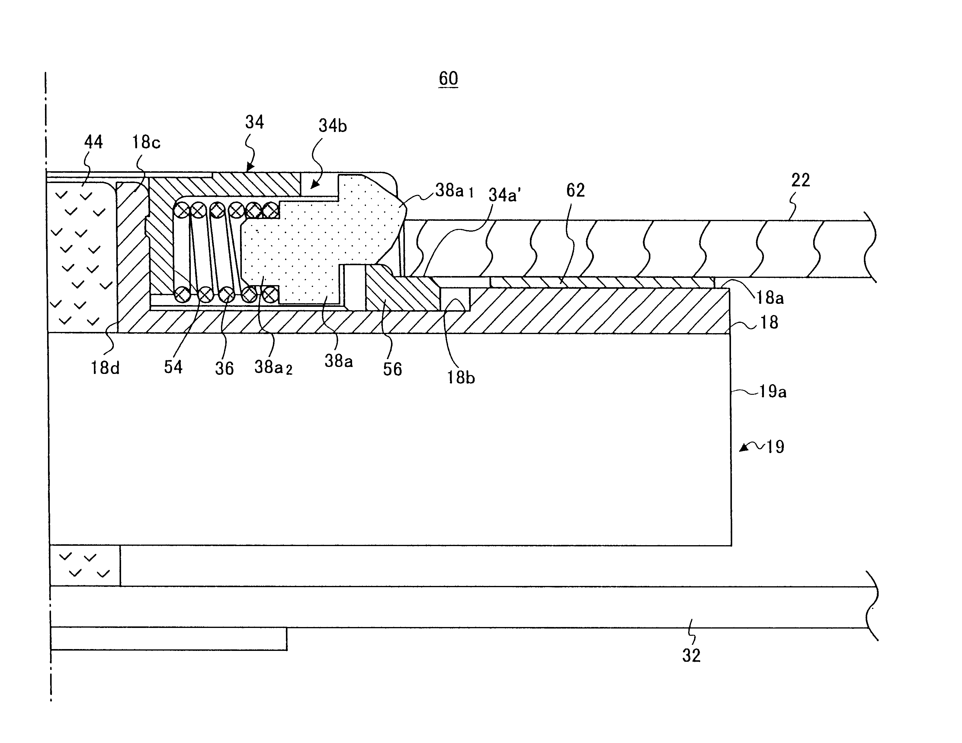
FIG. 9A is a plan view of a disk clamp apparatus of a second embodiment of the present invention. FIG. 9B is a side sectional view of the disk clamp apparatus of the second embodiment of the present invention. FIG. 10 is a greatly enlarged detailed vertical sectional view of a disk clamp part of a disk clamp apparatus of the second embodiment of the present invention. In this embodiment, parts that are the same as the parts shown in the first embodiment are given the same reference numerals, and explanation thereof will be omitted.

Referring to FIGS. 9A, 9B and 10, in a disk clamp apparatus of a second embodiment, a friction member 62 fixed on the disk mount surface 18a has an inner diameter having a larger diameter than the inner diameter of the disk 22. A guard part 34a′ projecting from an outer circumference of the clamper top 34 in a radial direction is extended to a position which faces to the innermost circumference part of the disk...

third embodiment

Next, the present invention will be described.

FIG. 11A is a plan view of a disk clamp apparatus of a third embodiment of the present invention. FIG. 11B is a side sectional view of the disk clamp apparatus of the third embodiment of the present invention. FIG. 12 is an enlarged perspective view of a clamper table 18 of a third embodiment. FIG. 13 is an enlarged vertical sectional view of a disk clamp part of the third embodiment. In this embodiment, parts that are the same as the parts shown in the first and second embodiments are given the same reference numerals, and explanation thereof will be omitted.

Referring to FIGS. 11A, 11B, 12 and 13, according to the disk clamp apparatus of the third embodiment 70, the friction member 42 fixed on the disk mount surface 18a has an inner diameter larger than an inner diameter of the disk 22. The clamper top 34 has a same configuration as the first embodiment. The clamper table 18 mounted and fixed on an upper surface of the disk driving moto...


PUM

PropertyMeasurementUnit
inner diameteraaaaaaaaaa
radiusaaaaaaaaaa

Abstract

A disk clamp apparatus, includes a disk mount surface part on which a record medium having a disk shape is mounted, the disk mount surface part including a part which faces an innermost circumference surface of the record medium, and a part which faces an outer circumference surface situated further out than the innermost circumference surface, wherein the part which faces the innermost circumference surface of the record medium has a same height as a height of the part which faces the outer circumference surface situated further out than the innermost circumference surface.

Description

BACKGROUND OF THE INVENTION1. Field of the InventionThe present invention generally relates to disk clamp apparatuses, and more particularly, to a disk clamp apparatus to clamp an inner circumference of a record medium having a disk shape which is mounted on a disk mount surface thereof.2. Description of the Related ArtFIG. 1A is a plan view of a conventional disk clamp apparatus and FIG. 1B is a side sectional view thereof. FIG. 2 is a greatly enlarged detailed vertical sectional view of a disk clamp part of the conventional disk clamp apparatus.Referring to FIGS. 1A, 1B and 2, the conventional disk clamp apparatus 1 includes a clamper table 4, a clamper top 5, and a clamp member 7, and a core adjusting member 9. The clamper table 4 is rotationally driven by a disk driving motor 3 mounted on a print board 2. The clamper top 5 projects on a center of the clamper table 4. The clamp member 7 is pushed in a radial direction by a spring force of a coil spring 6 provided inside of the cl...

Claims


Application Information

Patent Timeline
Patent Type & Authority Patents(United States)
IPC IPC(8): G11B17/022G11B17/028
CPCG11B17/0282G11B17/022G11B17/028
Inventor WATANABE, TAKASHIINOUE, SATORU
Owner TEAC CORP
Why Eureka
Try Eureka