
Condensate drain pan

a condensate and drain pan technology, applied in the field of condensate drain pans, can solve the problems of increasing the problem, cumbersome installation and fastening of the drain pan to the hvac unit, and affecting the quality of air in the home, so as to reduce the chance of microbial accumulation, and reduce the effect of microbial growth

Inactive Publication Date: 2005-03-22
AIR & LIQUID SYST LLC
View PDF8 Cites 69 Cited by
  • Summary
  • Abstract
  • Description
  • Claims
  • Application Information

AI Technical Summary

Benefits of technology

In accordance with the present invention, a condensate drain pan is provided which addresses and overcomes or minimizes the foregoing and other problems of the prior art. More particularly in this respect, a drain pan in accordance with the invention is operable to funnel and discharge condensate, thus to minimize or eliminate microbial accumulation. By minimizing or eliminating microbial accumulation, periodic chemical treatment or cleaning of the drain pan is minimized. Likewise, monitoring and / or adjustment of the pan after initial installation is also minimized. Accordingly, maintenance time and effort is advantageously reduced. The drain pan is constructed from a single piece of sheet material or multiple pieces of material, preferably metal, which are constructed to eliminate the potential for leakage or condensate settling or accumulation during use while facilitating the ease of manufacture and reducing the cost thereof. Further, the drain pan is usable with a wide variety of types and sizes of air handling units as an original or replacement part, thus providing a versatility not available with drain pans provided heretofore.
Yet another further object of the present invention is to provide a condensate drain pan effective for retrofit applications and / or replacements with respect to existing air handling units.

Problems solved by technology

Multiple components discharging condensation require multiple drain pans, thereby exasperating the problem that the drain pan is trying to resolve.
Additionally, multiple components make the installation and fastening of the drain pan to the HVAC unit cumbersome.
The drain hole or plug is conducive to not only microbial growth, but is also susceptible to eventual clogging of the opening.
This, in turn, will result in overflow of the condensate drain pan as well as accumulation of condensate within the HVAC unit and to the surrounding space.
There are also other problems which commonly occur with condensate drain pans.
A unit with a relatively high air flow may cause the condensate to blow out of the condensate drain pan if the water level is too high.
In addition, depending on where the condensate drips onto the drain pan, some existing configurations may serve some types of HVAC units adequately, whereas the same drain pan configuration will be ineffective on another type of HVAC unit.
This approach not only results in one or more drain outlets not being used, but also results in an additional fixture by which condensate can accumulate resulting in microbial growth.
This process not only involves a time-consuming step of cleaning the drain pan, but also involves the secondary step of periodically applying chemicals.
Additionally, the use of chemicals in this process also affects the indoor air quality due to the fact that the HVAC unit has an intake which consumes the surrounding chemically-altered air.

Method used


Image

  • Condensate drain pan
  • Condensate drain pan
  • Condensate drain pan

Examples


Embodiment Construction

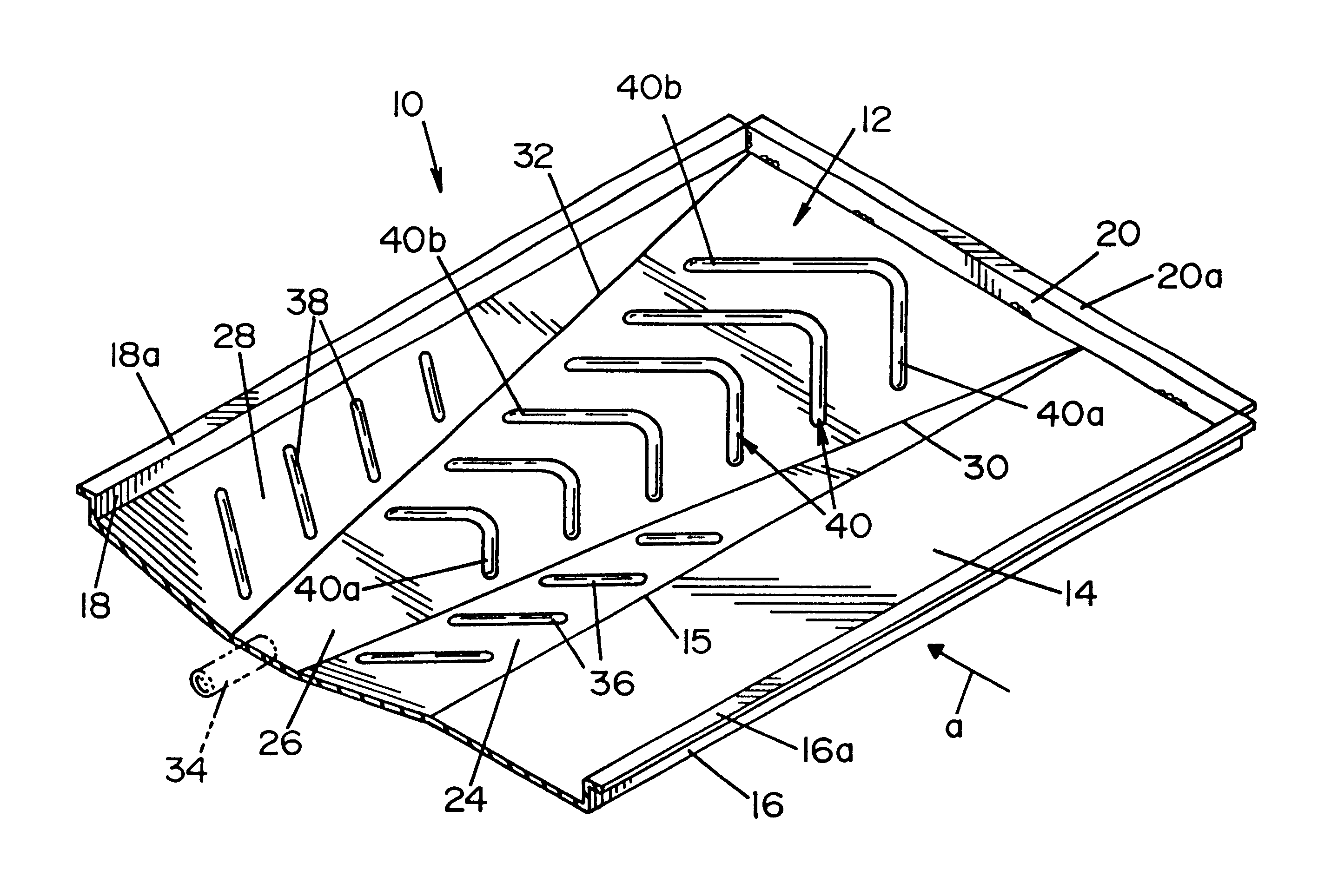
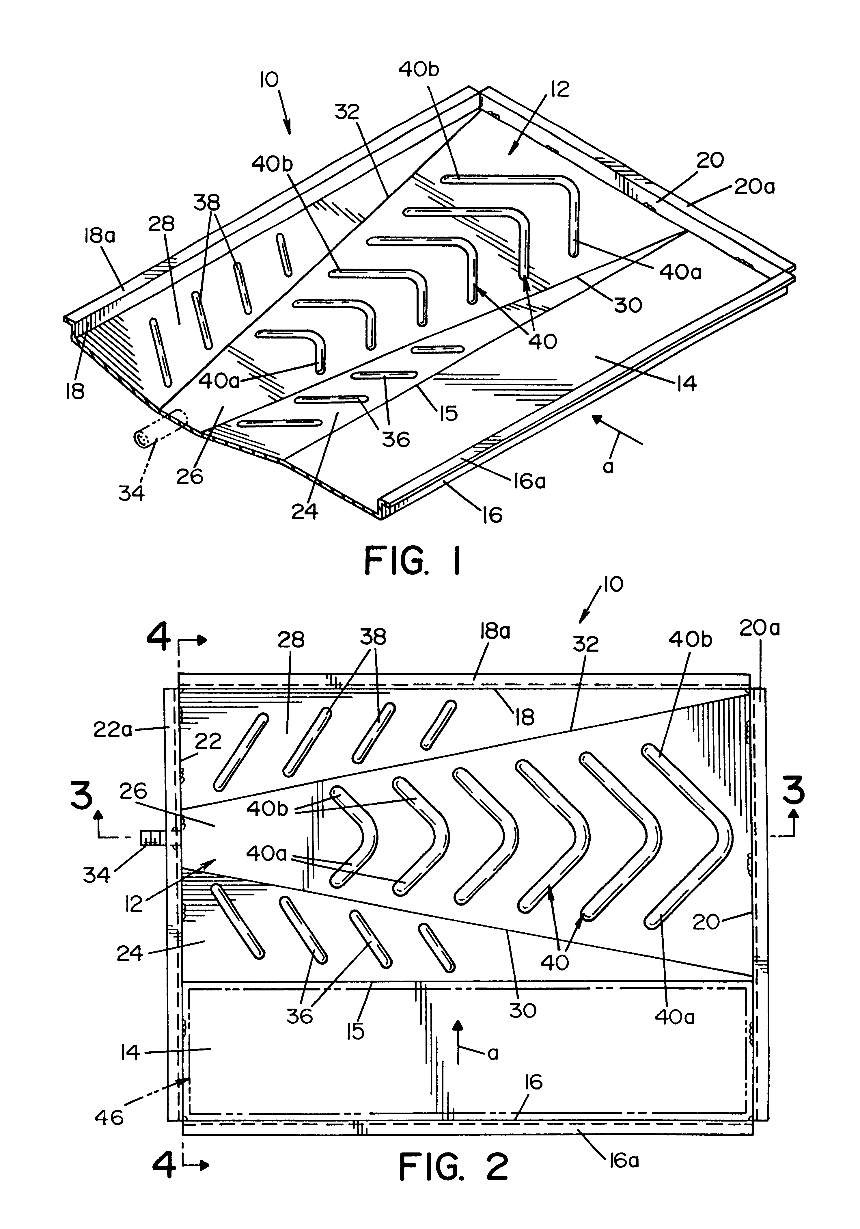
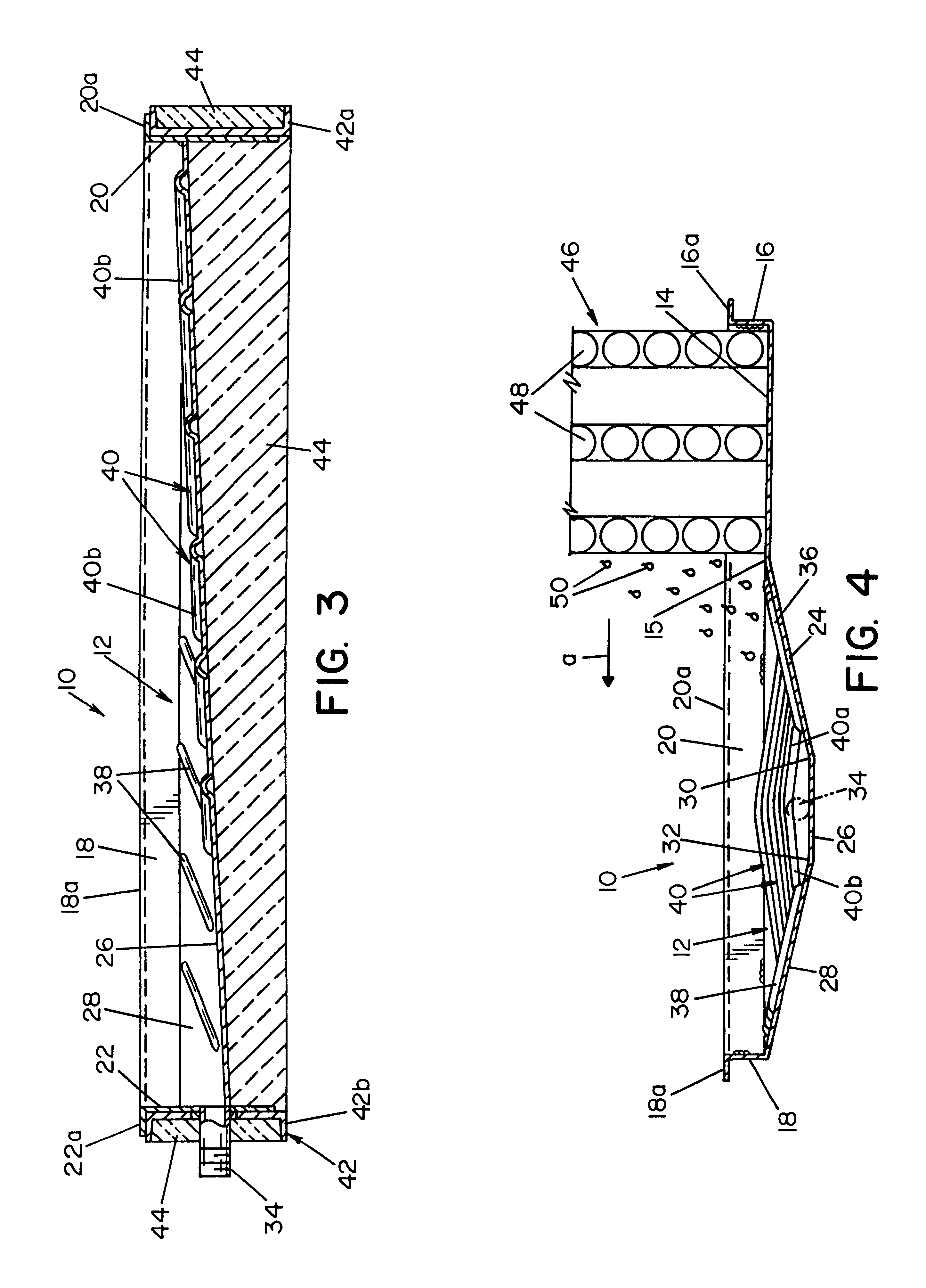
Referring now in greater detail to the drawings wherein the showings are for the purpose of illustrating a preferred embodiment of the invention only and not for the purpose of limiting the invention, a condensate drain pan 10 in accordance with the invention comprises a compound-sloped floor surface 12 and a laterally adjacent flat floor surface 14 bounded by an upwardly extending peripheral wall defined by a front wall 16, a back wall 18 and opposite side walls 20 and 22. Flat floor surface 14 is located on the upstream side of airflow a Each of the foregoing walls has an upper end terminating in a corresponding outwardly extending flange respectively designated 16a, 18a, 20a, and 22a. Compound-sloped floor surface 12 includes three faces 24, 26, and 28, each of which is generally triangular in peripheral contour. Face 24 slopes downwardly and inwardly from the inner edge 15 of floor surface 14, face 26 slopes downwardly from side wall 20 to side wall 22, and face 28 slopes downwa...


PUM


Abstract

A condensate drain pan comprises a compound-sloped floor surface having intersecting sloped faces which slope from a high point to a low point. The intersecting sloped faces form creases therebetween to facilitate condensate elimination, and the floor surface includes condensate directing embossments which further facilitate condensate elimination. The condensate drains to a drain opening at the low point.

Description

This invention relates generally to condensate drain pans for air handling units, and more specifically, to a compound-sloped condensate drain pan able to eliminate accumulations of water at the base of an air handling unit.The invention is particularly applicable to and will be described with specific reference to draining condensate from air handling units. However, those skilled in the art will recognize that the invention may have broader applications and could be utilized in other areas where eliminating accumulation of fluids is desired.BACKGROUND OF THE INVENTIONThe air conditioning industry has come under heightened scrutiny to improve indoor air quality, particularly relating to health risks that have been identified as resulting from microbial and mold growth from standing condensate in air conditioning units. Typically, the standing condensate remains in the drain pans during and after the air conditioning unit's run cycle. This accumulation of condensate allows the micro...

Claims


Application Information

Patent Timeline
IPC IPC(8): F24F13/22F24F13/00
CPCF24F13/222
Inventor MCNEIL, DONALD A.WAKEFIELD, JAMES M.LAND, JAMES C.
Owner AIR & LIQUID SYST LLC
Learn More