Vacuum cleaner having an ion generator

a vacuum cleaner and generator technology, applied in vacuum cleaners, carpet cleaners, suction cleaners, etc., can solve the problem of unsanitary needless to say, and achieve the effect of improving the air quality of the room

Inactive Publication Date: 2007-02-13
PANASONIC CORP
View PDF24 Cites 15 Cited by
  • Summary
  • Abstract
  • Description
  • Claims
  • Application Information

AI Technical Summary

Benefits of technology

[0009]It is, therefore, a primary object of the present invention to provide a user-friendly vacuum cleaner including an ion generator, improving room air quality.

Problems solved by technology

Moreover, when dirt accumulated in the filter bag 12 is not disposed of relatively frequently, saprophytes may breed therein and be discharged via the exhaust outlets 9 during the operation of the vacuum cleaner, which needless to say is very unsanitary.

Method used


Image

  • Vacuum cleaner having an ion generator
  • Vacuum cleaner having an ion generator
  • Vacuum cleaner having an ion generator

Examples


Embodiment Construction

[0057]Preferred embodiments of the present invention will now be described in detail with reference to the accompanying drawings, wherein like reference numerals appearing in FIGS. 1 to 20C represent like parts.

[0058]A first preferred embodiment of the present invention will now be described in detail with reference to FIG. 3.

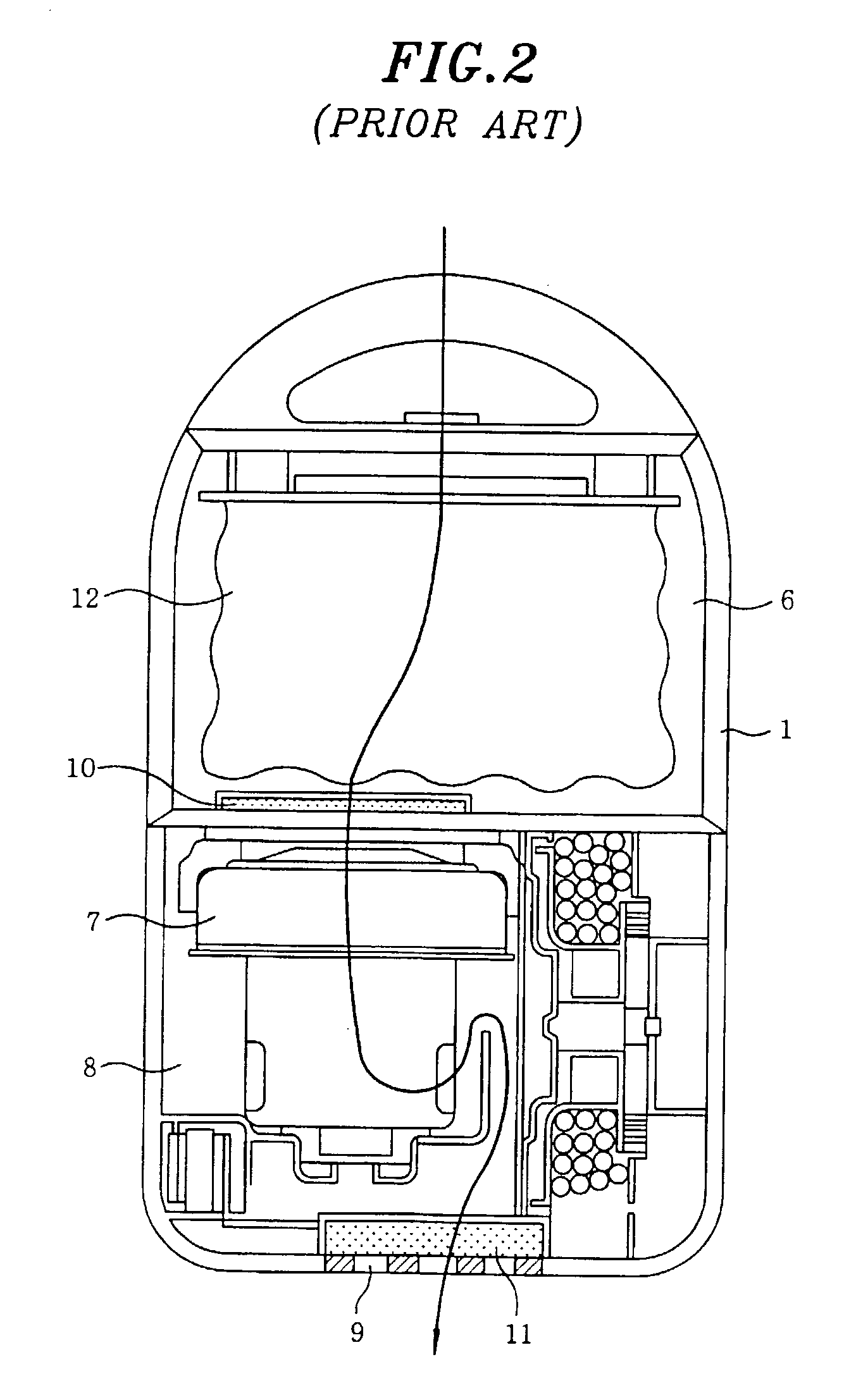
[0059]Referring to FIG. 3, there is shown a schematic internal structure of a main body 1 of a vacuum cleaner in accordance with the first preferred embodiment of the present invention. The main body 1 includes a dirt collection chamber 6, a filter bag 12 disposed in the dirt collection chamber 6 as a dirt collecting means for capturing and collecting dirt therein, an electric blower 7 for generating a suction, creating an air flow and forcibly drawing in dirt, an electric blower chamber 8 for mounting therein the electric blower 7, and an exhaust unit having exhaust outlets 9 for discharging the drawn air to atmosphere therethrough.

[0060]Reference numerals 10 ...


PUM


Abstract

A vacuum cleaner includes an electric blower for generating a suction air flow, a suction head in communication with the electric blower for drawing in dirt, a filter bag communication with the electric blower for capturing and collecting dirt, an exhaust unit for discharging exhaust air from the electric blower to atmosphere, and an ion generator for generating negative ions and/or positive ions. The ion generator is placed between the suction head and the filter bag.

Description

FIELD OF THE INVENTION[0001]The present invention relates to a vacuum cleaner; and, more particularly, to a vacuum cleaner having at least one ion generator for generating negative ions and / or positive ions.BACKGROUND OF THE INVENTION[0002]Referring to FIGS. 1 and 2 there are shown a perspective view of a typical vacuum cleaner and a schematic internal structure of a main body thereof as described in Japanese Laid-Open Publication No. 1987-109531, respectively.[0003]As shown in FIG. 1, the typical vacuum cleaner includes a main body 1 having a dirt collection chamber 6 provided with a connection port 1A; an extension tube 3 provided with a handle 5 at one of its ends for controlling an electric blower 7 as will be described; a suction head 4, installed at the other end of the extension tube 3, for an intake of dirt entraining air; and a hose 2 for interconnecting the connection port 1A to the handle 5, whereby an air-flow path is provided between the main body 1 and the suction head...

Claims


Application Information

Patent Timeline
Patent Type & Authority Patents(United States)
IPC IPC(8): A47L9/04A47L7/04A47L9/06
CPCA47L9/0488A47L9/06A47L9/0411A47L7/04A47L9/0613
Inventor SOEJIMA, MASAKUNIKONDO, YASUSHITANIGUCHI, YOSHIHIROYOSHIDA, RYOHEISHIBUYA, MASAKIYAMAGUCHI, SEIJIKAJIKAWA, SABUROKITAMURA, HIDENORIURATANI, HIROYUKIFUJITA, KOUICHIISHIKAWA, HARUKA
Owner PANASONIC CORP
Why Eureka
Try Eureka