Missile with odd symmetry tail fins

a technology of tail fins and missiles, applied in the direction of projectiles, weapons, direction controllers, etc., can solve the problem of longer signal integration times

Inactive Publication Date: 2005-03-22
RAYTHEON CO
View PDF13 Cites 61 Cited by
  • Summary
  • Abstract
  • Description
  • Claims
  • Application Information

AI Technical Summary

Benefits of technology

According to a further aspect of the invention, a tail assembly for a guidable projectile, includes a base fixedly connected to the body; a fin retainer; an odd number of fins coupled

Problems solved by technology

However, they may have longer signal integration times, and may indeed have requirements for stabi

Method used


Image

  • Missile with odd symmetry tail fins
  • Missile with odd symmetry tail fins
  • Missile with odd symmetry tail fins

Examples


Embodiment Construction

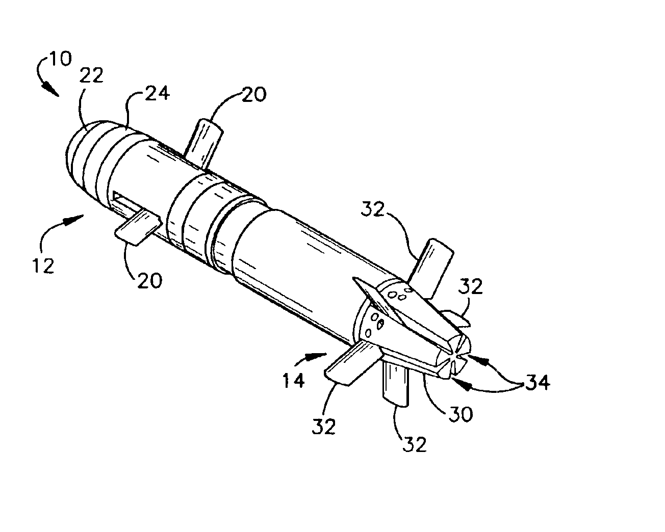
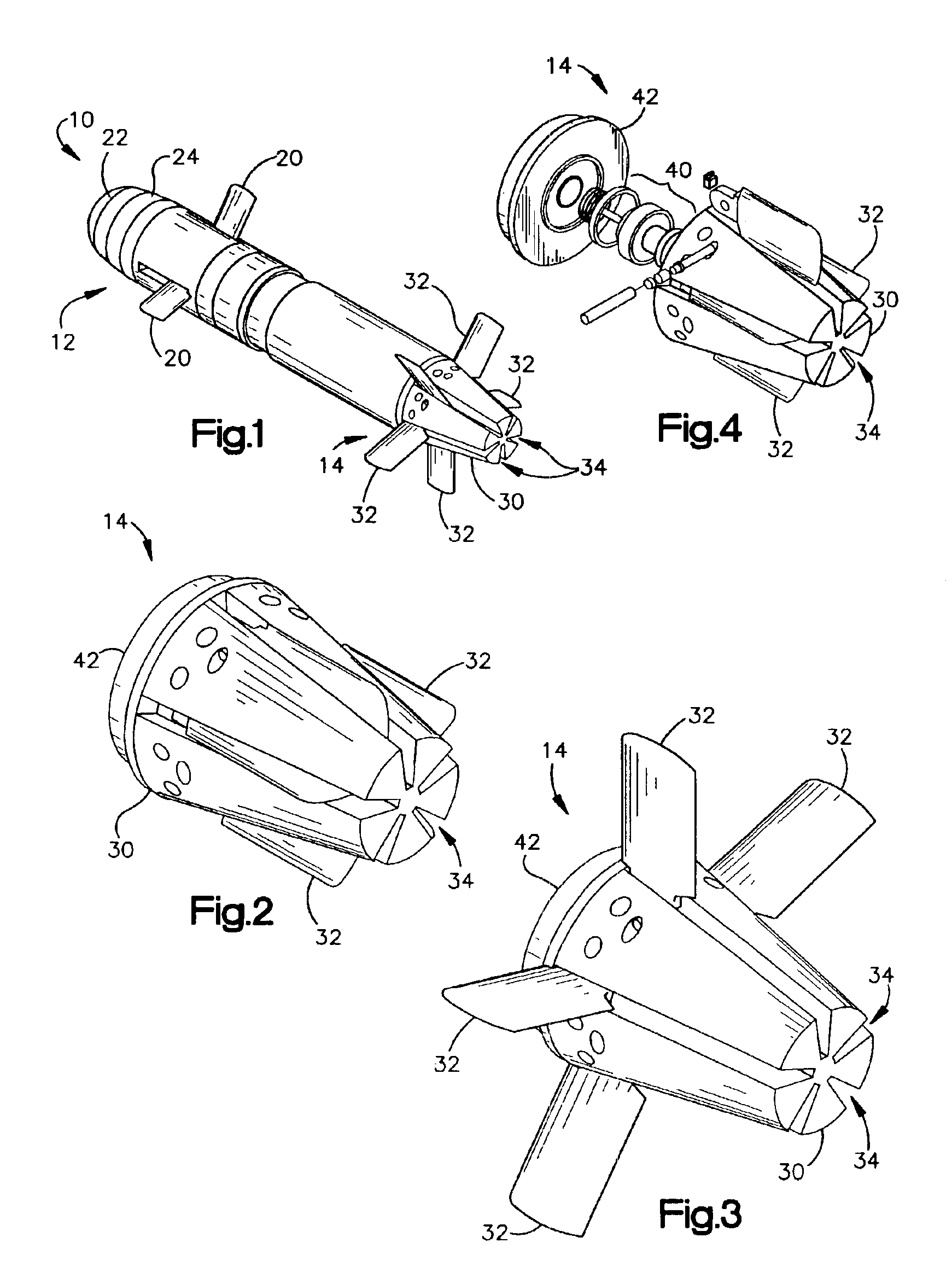
A missile, either a powered missile or an unpowered projectile, includes a freely-rolling tail assembly having an odd number of fins. Having an odd number of fins may reduce oscillations caused by the rotation of the freely-rotating tail. This may make a more stable platform for a seeker, such as an uncooled focal point array or other imaging infrared (IIR) or millimeter wave radio frequency (MMW) seeker, in the body of the missile. Also, minimizing oscillation by using an odd number of fins may facilitate control of the missile.

Referring initially to FIG. 1, a missile 10 includes a forward body 12 coupled to an aft rolling tail assembly 14. The term “missile”, as used herein, is intended to encompass both thrust-producing and unpowered devices. Thus, the missile 10 may either be an unpowered projectile, for example, fired from a gun or other launcher, or alternatively may be a powered missile, for example, containing a rocket motor, jet engine, or other thrust-producing device.

The ...


PUM


Abstract

A missile, either a powered missile or an unpowered projectile, includes a freely-rolling tail assembly having an odd number of fins. Having an odd number of fins may reduce oscillations caused by the rotation of the freely-rotating tail. This may make a more stable platform for a seeker, such as an uncooled focal point array or other imaging infrared (IIR) or millimeter wave radio frequency (MMW) seeker, in the body of the missile. Also, minimizing oscillation by using an odd number of fins may facilitate control of the missile.

Description

BACKGROUND OF THE INVENTION1. Technical FieldThe invention relates to powered and unpowered missiles having freely rolling tails.2. Description of the Related ArtGuided missiles and projectiles have previously utilized simple gimbaled semi-active laser (SAL) terminal seekers for guidance to a target or other desired location. SAL seekers provide some measure of guidance, while maintaining loose requirements in terms of induced pointing errors, errors due to undesired changes in orientation of the seeker. More recently, imaging infrared (IIR) and millimeter wave radio frequency (MMW) seekers have been employed. Among these new types of seekers are uncooled focal point array seekers, which are a type of IIR seeker. Such new seekers may reduce cost, weight, power requirements and / or complexity. However, they may have longer signal integration times, and may indeed have requirements for stability that are a factor of ten more stringent than with older types of seekers, such as SAL seeke...

Claims


Application Information

Patent Timeline
IPC IPC(8): F42B10/00F42B10/06
CPCF42B10/06
Inventor GESWENDER, CHRIS EUGENEHARLINE, SHAWN BRENTBLAHA, GEORGE A.
Owner RAYTHEON CO
Why Eureka
Try Eureka