
Pipe joint

a pipe joint and pipe joint technology, applied in the direction of pipe joints, fluid pressure sealed joints, sleeves/socket joints, etc., can solve the problems of pipe joints not being able to achieve preventing effect, pipe joints cannot be mounted to fluid pressure apparatuses, and pipe joints cannot be mounted to them

Inactive Publication Date: 2005-03-22
SMC CORP
View PDF14 Cites 36 Cited by
  • Summary
  • Abstract
  • Description
  • Claims
  • Application Information

AI Technical Summary

Benefits of technology

It is a technical object of the present invention to reliably mount a pipe joint into a joint mounting hole of a fluid pressure apparatus while preventing pulling-out of the pipe joint even if there are slight dimensional differences due to tolerances and errors between the pipe joint and the joint mounting hole of a fluid pressure apparatus.
The pipe joint having the above structure is mounted to the fluid pressure apparatus by inserting the joint body into the joint mounting hole of the fluid pressure apparatus and the piping tube is connected to the tube connecting hole. At this time, the pull-out preventing ring mounted to the outer periphery of the joint body is elastically press-fitted in the joint mounting hole by elastic deformation in the radial direction and the annular edge(s) on the outer peripheral face is(are) locked to the hole wall of the joint mounting hole. Therefore, even if there are some dimensional differences due to tolerances, errors, and the like between the pipe joint and the joint mounting hole, such differences are absorbed by elasticity of the pull-out preventing ring, the pull-out preventing ring is reliably fitted in the joint mounting hole, and the annular edge(s) is(are) locked to the hole wall. If an external force in such a direction as to pull the pipe joint out of the joint mounting hole acts on the pipe joint through the tube, the pipe joint is prevented from being pulled out of the joint mounting hole by locking of the annular edge(s).

Problems solved by technology

Therefore, the pipe joint cannot be mounted to the joint mounting hole if they are of different dimensions.
The pull-out prevention cannot be locked to the hole wall of the joint mounting hole or, on the contrary, the pull-out prevention lodges in the joint mounting hole and the pipe joint cannot be mounted.
Therefore, it is quite conceivable that the pull-out prevention does not effectively function and therefore a reliable pull-out preventing effect cannot be obtained or that the pipe joint cannot be mounted to the fluid pressure apparatus depending on the tolerances and errors of both the members.

Method used


Image

  • Pipe joint
  • Pipe joint
  • Pipe joint

Examples


Embodiment Construction

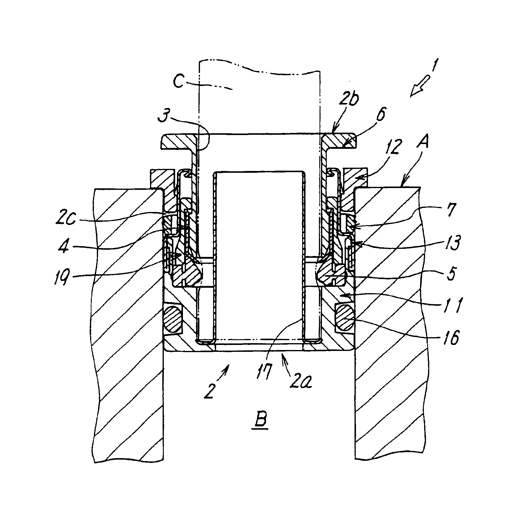
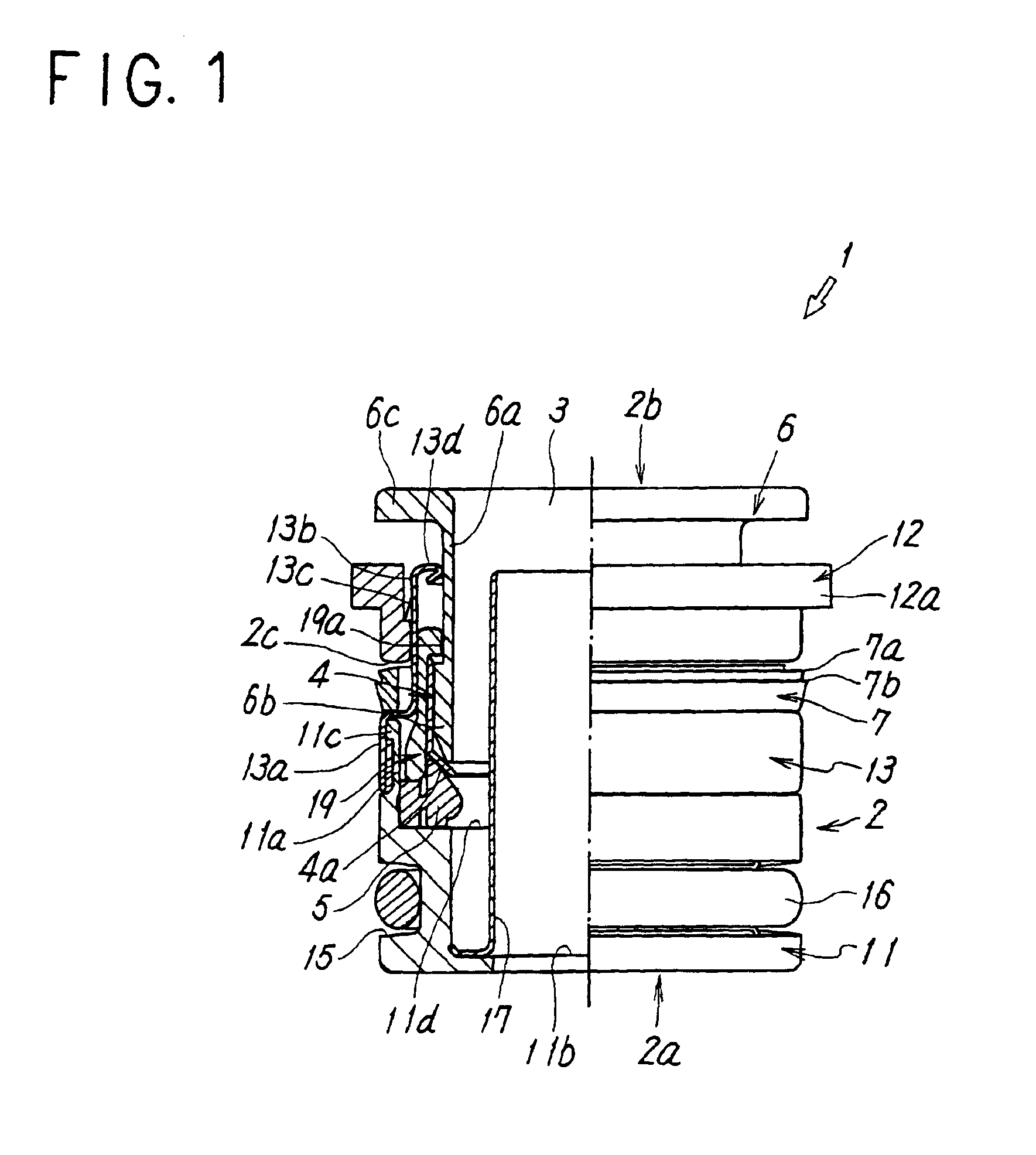
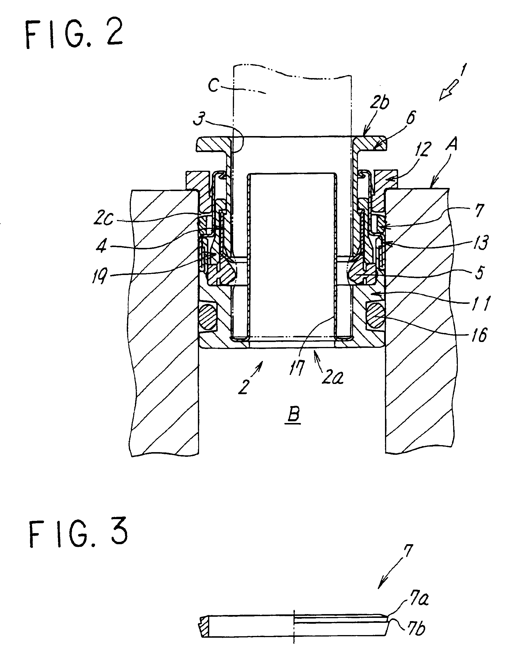
FIGS. 1 and 2 show an embodiment of a pipe joint of the present invention. The pipe joint 1 has a cylindrical joint body 2 to be inserted into a joint mounting hole B of a fluid pressure apparatus A. The joint body 2 includes a first end 2a on one of an axial direction side and a second end 2b on an opposite side, is inserted into the joint mounting hole B of the fluid pressure apparatus A from the first end 2a, and is formed of a first body portion 11 positioned on the first end 2a side, a second body portion 12 positioned on the second end 2b side, and an intermediate third body portion 13 connecting both the body portions 11 and 12.

The first body portion 11 is made of metal or synthetic resin and has a seal groove 15 surrounding an outer periphery of the portion 11. An O-ring 16 is provided in the seal groove 15 and the O-ring 16 provides sealing between an outer peripheral face of the joint body 2 and an inner peripheral face of the joint mounting hole B. In the first body porti...


PUM


Abstract

A recessed portion is formed on an outer periphery of a cylindrical joint body to be inserted into a joint mounting hole of a fluid pressure apparatus. A pull-out preventing ring which is formed separately from the joint body can be deformed elastically in a radial direction, and has one or more annular edge(s) on an outer peripheral face which is fitted in the recessed portion and over the outer periphery of the joint body. The annular edge(s) of the pull-out preventing ring is(are) locked to a hole wall of the joint mounting hole when a force in such a direction as to pull out the pipe joint acts on the pipe joint.

Description

TECHNICAL FIELDThe present invention relates to a pipe joint used for connecting a piping tube to a fluid pressure apparatus of various kinds in a fluid pressure circuit using fluid pressure such as air pressure and hydraulic pressure.BACKGROUND ARTConventionally, in general, a quick-connecting-type pipe joint is used to connect a piping tube to a piping connecting hole of a fluid pressure apparatus. The pipe joint is mounted by press-fitting a cylindrical joint body into the pipe connecting hole (joint mounting hole) of the fluid pressure apparatus. At this time, a pull-out prevention formed of a claw, a projection, or the like is formed on an outer peripheral face of the joint body and locked to a hole wall of the joint mounting hole to thereby prevent the pipe joint from pulling-out of the mounting hole.However, in the above conventional pipe joint, the pull-out prevention is formed integrally with the joint body and the joint bodies are of a uniform outside diameter. Therefore, ...

Claims


Application Information

Patent Timeline
Patent Type & Authority Patents(United States)
IPC IPC(8): F16L37/00F16L37/091F16L37/12F16L17/00F16L21/02
CPCF16L37/091F16L37/0915F16L21/02
Inventor MATSUSHITA, KAZUHIRO
Owner SMC CORP
Learn More