Bracket attaching structure

a technology of brackets and fixing parts, applied in the direction of roofs, transportation and packaging, vehicle arrangements, etc., can solve the problem of increasing the production cost of the vehicle body

Active Publication Date: 2005-03-22
SUZUKI MOTOR CORP
View PDF19 Cites 20 Cited by
  • Summary
  • Abstract
  • Description
  • Claims
  • Application Information

AI Technical Summary

Benefits of technology

The invention has been carried out in view of the problem and it is an object thereof to provide a bracket attaching structure for ensuring a space of arranging a part of a curtain air bag or the like at a roof side rail portion without changing a shape of a body of a conventional art.

Problems solved by technology

Further, when a vehicle body mounted with a curtain air bag and a vehicle body which is not mounted with the curtain air bag are designed separately, production cost of the vehicle body is increased.

Method used


Image

  • Bracket attaching structure
  • Bracket attaching structure
  • Bracket attaching structure

Examples


Embodiment Construction

A bracket attaching structure of an embodiment of the present invention will be explained in reference to the drawings as follows.

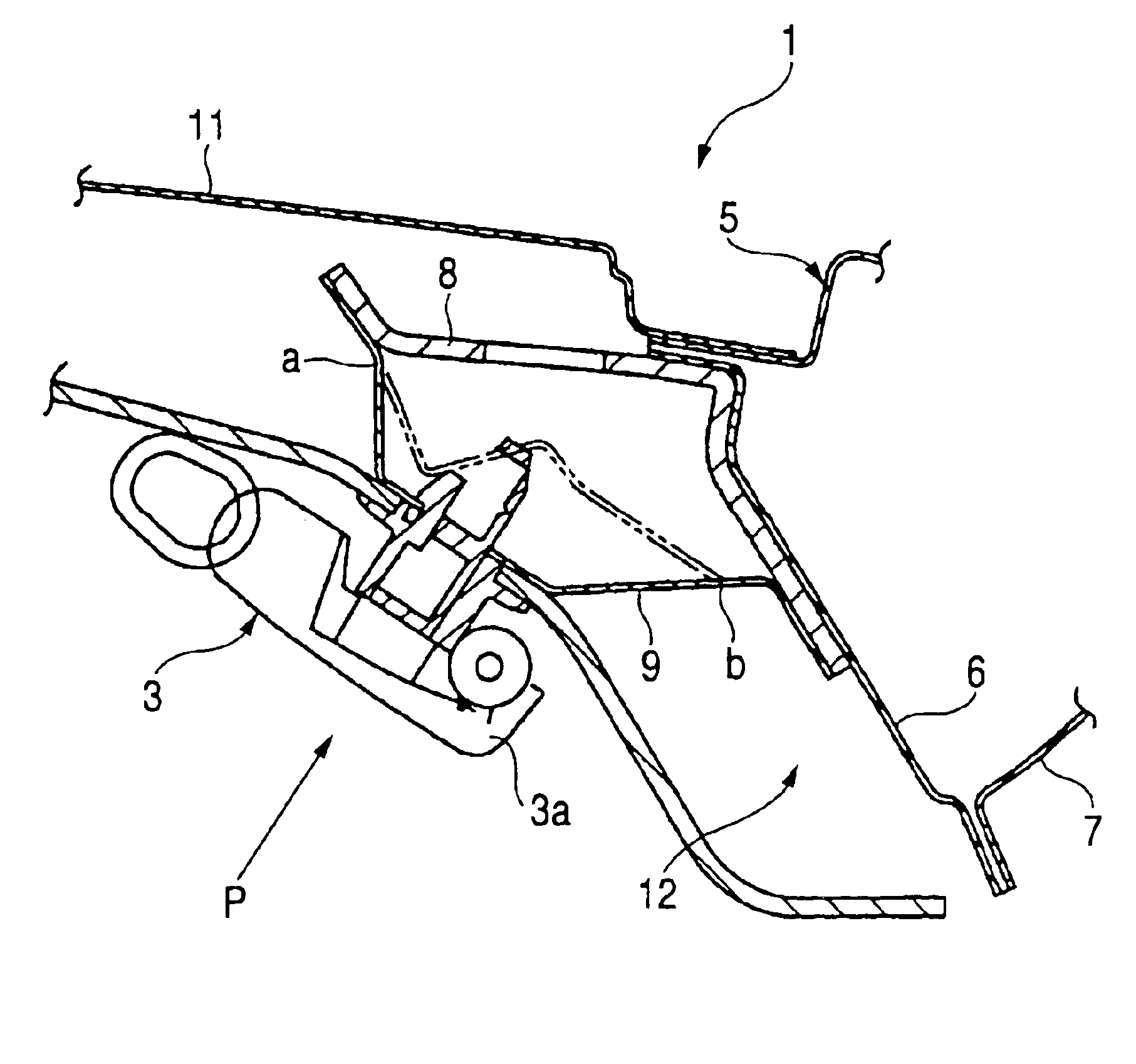
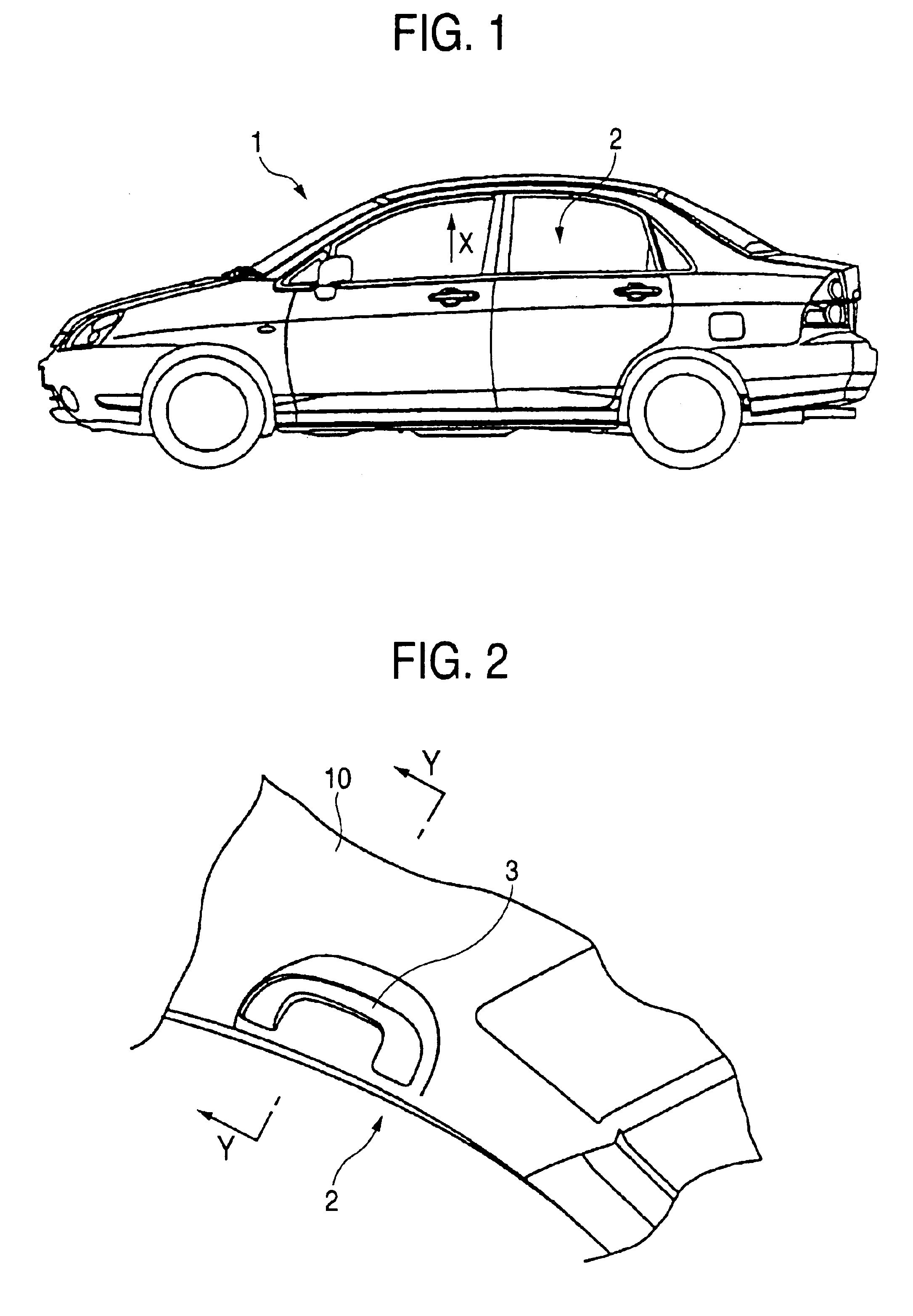
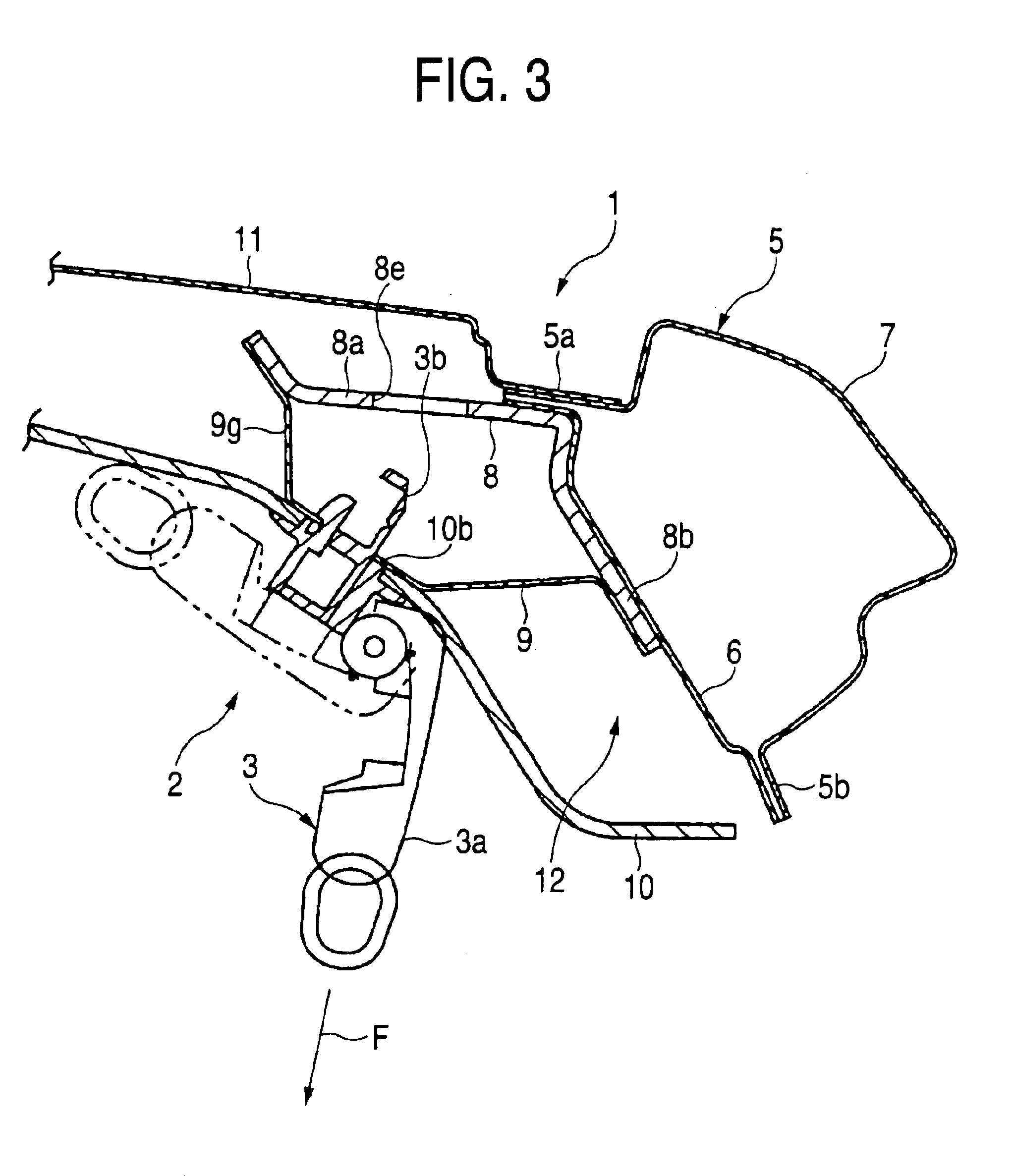
FIG. 1 shows an vehicle 1 according to the invention and FIG. 2 shows an assistant grip 3 arranged at a side portion of a roof of an inner vehicle compartment 2 of the vehicle 1. As is well known, the assistant grip 3 is mounted with an object of achieving stability of attitude by being grasped by a passenger.

FIG. 3 is a sectional view taken along a vehicle width direction showing a state of mounting the assistant grip 3. As illustrated in the drawing, a roof side rail portion 5 of the vehicle 1 forms a closed sectional space by overlapping a roof side inner panel 6 and two upper and lower end bonding portions 5a and 5b of a side body outer panel 7 projected to an outer side to bond by welding. An attaching bracket of the assistant grip 3 is provided on an inner compartment side of the roof side inner panel 6 and the attaching bracket is constituted by a ...


PUM


Abstract

A closed section is formed by bonding upper end portions and lower end portions of respectives of a roof side inner panel and a side body outer panel of an vehicle. A base bracket attached to a roof side inner panel for mounting an assistant grip and a grip bracket attached to the base bracket are provided to a side of an inner vehicle compartment of the roof inner panel. Further, a beam portion of the base bracket is fixed to the roof side inner panel to project to an upper side or a side of a vehicle compartment of an upper end portion side bonding portion of the roof side inner panel and the side body outer panel.

Description

BACKGROUND OF THE INVENTIONThe present invention relates to a bracket attaching structure of an attaching bracket for forming a closed section by a roof side inner panel and a side body outer panel of a vehicle and mounting an assistant grip to an inner compartment side of a roof inner panel.FIG. 11 is a sectional view of a roof side rail portion 51 of a vehicle in a conventional art. As disclosed in JP-A-10-181490 (Japanese Patent Application Publication Number: Hei10-181490) and FIG. 11, in a vehicle structure of a conventional art, the roof side rail portion 51 forms a closed section 57 by bonding two upper and lower end portions of a roof side inner panel 52 and a side body outer panel 53. An attaching bracket 54 having substantially a hat-like sectional shape is fixed to an inner compartment side of the roof side inner panel 52 by welding. The attaching bracket 54 is for attaching an assistant grip, not illustrated, (refer to an assistant grip 3 of FIG. 2), an attaching hole 54...

Claims


Application Information

Patent Timeline
Patent Type & Authority Patents(United States)
IPC IPC(8): B60N3/02B62D25/06
CPCB60N3/026
Inventor ITO, OSAMUHOSHINO, MASAHARUHORI, TORUHATONO, KENICHIRO
Owner SUZUKI MOTOR CORP
Why Eureka
Try Eureka