Vehicle body structure

a technology for vehicles and body parts, applied in the direction of roofs, transportation and packaging, vehicle arrangements, etc., can solve the problems of front wheels having a high possibility of partially coming into contact with the front end of the side sill, and achieve the effects of less penetration, increased strength of left and right side sills, and improved passenger compartment spa

Inactive Publication Date: 2014-02-11
HONDA MOTOR CO LTD
View PDF12 Cites 15 Cited by
  • Summary
  • Abstract
  • Description
  • Claims
  • Application Information

AI Technical Summary

Benefits of technology

[0009]The front ends of the left and right side sills are formed not into square-shaped closed cross sections like the rear ends, but into closed cross sections and upside-down inverted-L shapes. In other words, the upside-down inverted-L shaped cross sections are cross sections contained within a range whereby there is a high possibility that the retracted front wheels will come in contact along with the rearward deformation of the front part of the vehicle body when the vehicle has undergone a front-surface collision. Therefore, when the retracted front wheels have come in contact with the front ends of the side sills during the front-surface collision of the vehicle, the collision force (external force) from the front of the vehicle can be borne throughout nearly the entire front ends of the side sills, or, in other words, throughout nearly their entire surfaces. Furthermore, the areas from the front ends to the rear ends of the left and right side sills are formed into closed cross sections which smoothly (gradually) change from upside-down inverted-L shaped cross sections to square-shaped cross sections. Therefore, external force that acts on the front ends is transferred in a substantially uniform manner through the entire periphery of the closed cross sections in any region from the front ends to the rear ends. Consequently, external force from the front is efficiently transferred from the front ends to the rear ends of the side sills, whereby the external force can be borne by the entire side sills. As a result, the performance of the side sills in absorbing the external force can be ensured while also ensuring the strength of the side sills. Moreover, since the external force can be borne by the entire side sills, excess thickness that does not bear the external force can be eliminated from the hollow side sills. In other words, the thickness of the side sills can be reduced. As a result, it is possible to reduce the weight of the vehicle body.
[0020]It is also preferred that the left and right center pillars be reinforced by the stiffeners and the floor panel have vehicle widthwise ends positioned at bottom ends of the upright side part, with inclined side parts extending from the bottom ends to vehicle widthwise outer ends of the lateral side parts and joined to the stiffeners. Thus, when the vehicle under goes a side collision, external force from the side of the vehicle is transferred from the center pillars to the stiffeners, then from the stiffeners to the vehicle widthwise ends of the floor panel via the inclined side parts, and finally from the floor panel to other members. The twisting of the side sills into the passenger compartment due to the side external force is suppressed by the inclined side parts and the floor panel. As a result, since there is less penetration when the center pillars collapse and penetrate into the passenger compartment due to a side collision, the space in the passenger compartment can be better ensured. Moreover, the strength of the side sills can be reduced because the twisting of the side sills is suppressed by the inclined side parts and the floor panel. The thickness of the side sills, for example, can be reduced proportionately. Thus, the strength of the side sills can be ensured, and the weight of the side sills can be reduced as well.

Problems solved by technology

In other words, the front wheel has a high possibility of partially coming in contact with the front end of the side sill.

Method used


Image

  • Vehicle body structure
  • Vehicle body structure
  • Vehicle body structure

Examples


Embodiment Construction

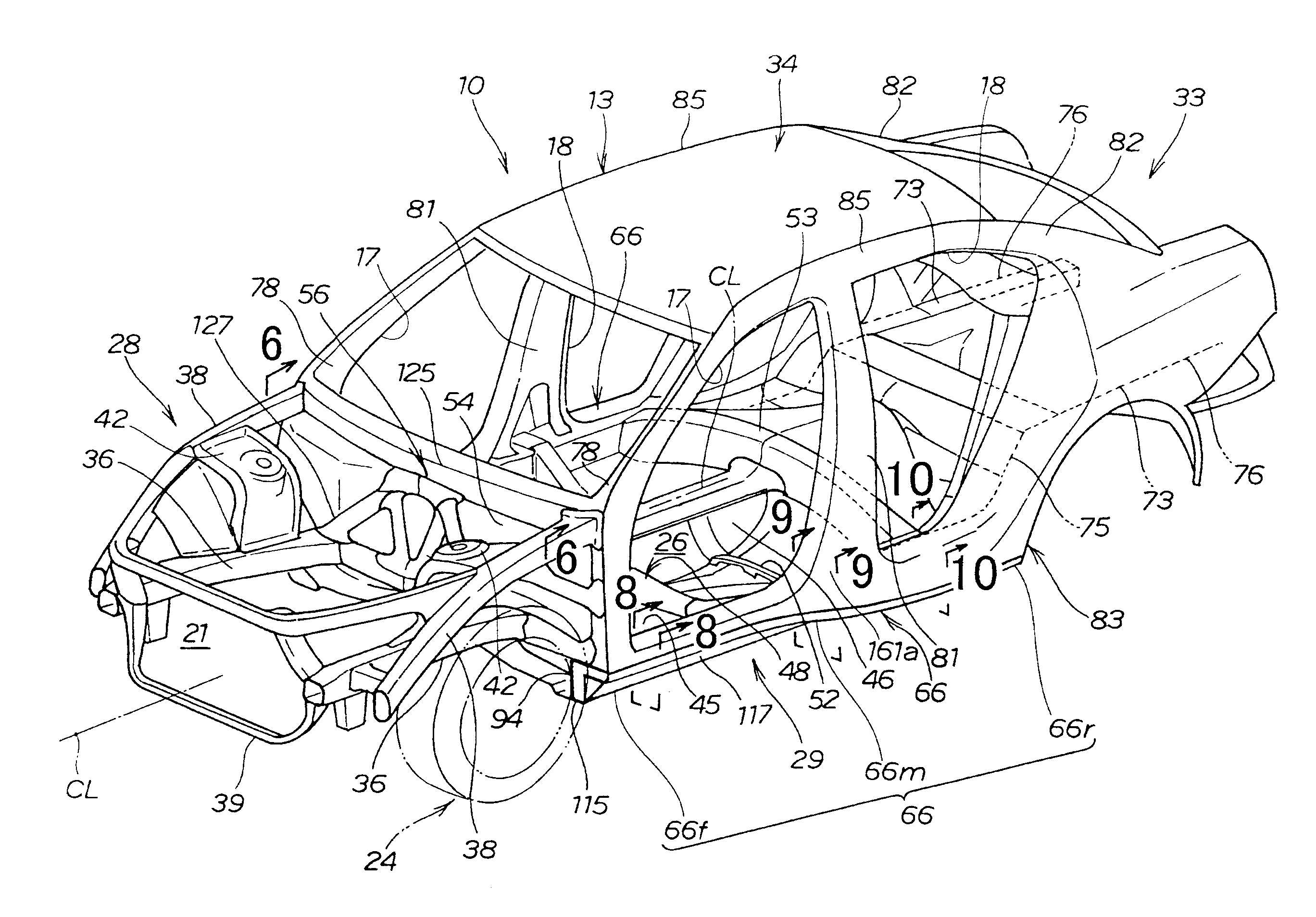
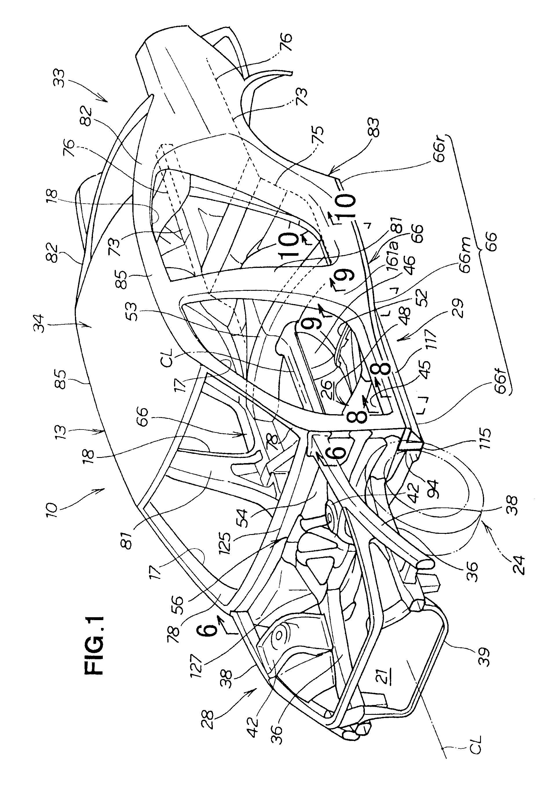
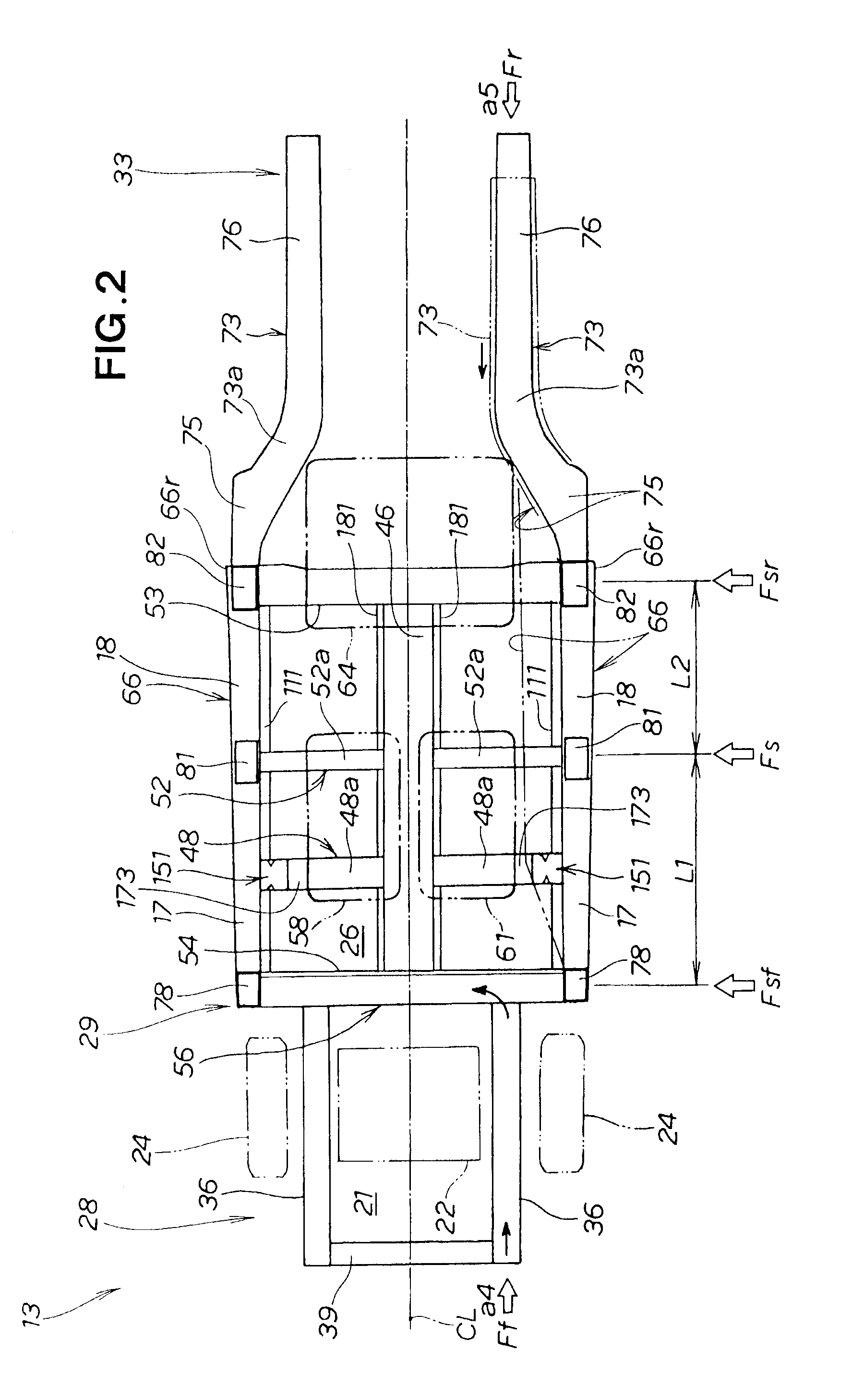
[0036]A vehicle 10 is a four-door type passenger vehicle as shown in FIGS. 1, 2, and 3, wherein a front engine compartment 21 and a passenger compartment 26 located directly behind the engine compartment 21 are formed inside a vehicle body 13.

[0037]The vehicle body 13 is of a monocoque construction, and is formed into a bilaterally symmetrical shape about a vehicle width center line CL extending in the vehicle longitudinal direction through the widthwise center of the vehicle 10. The vehicle body 13 has front door openings 17, 17 and rear door openings 18, 18 in the left and right side surfaces. The front and rear door openings 17, 18 are opened and closed by doors (not shown). A power unit 22 is disposed in the engine compartment 21. The power unit 22 is composed of an engine and a transmission. Left and right front wheels 24, 24 are suspended on the left and right sides of a front part 28 of the vehicle body 13.

[0038]The front part 28 of the vehicle body 13 is a portion where the ...


PUM


Abstract

A vehicle body includes hollow left and right side sills. Front ends of the side sills are formed into closed cross sections and substantially inverted-L shapes. The front end of the right side sill is bilaterally symmetrical to the front end of the left side sill. Rear ends of the left and right side sills are formed into substantially square-shaped cross sections. Portions from the front ends to the rear ends of the side sills are formed into closed cross sections which change smoothly from the inverted-L shaped cross sections to the square-shaped cross sections.

Description

FIELD OF THE INVENTION[0001]The present invention relates to a body structure for a passenger vehicle or the like.BACKGROUND OF THE INVENTION[0002]Left and right side sills of a vehicle body are positioned on the left and right sides of the vehicle body, and the side sills extend in a longitudinal direction. Requirements of the left and right side sills in all of the following three cases are that it be possible to guarantee a certain strength, and also that it be possible to guarantee collision force absorbing performance. The first is a case of a so-called front-surface collision, in which collision force acts on the front surface of the vehicle. The second is a case of a so-called rear-surface collision, in which a collision force acts on the rear surface of the vehicle. The third is a case of a so-called side collision, in which collision force acts on the side surface in the width direction of the vehicle.[0003]For example, when the vehicle undergoes a side collision, it is pos...

Claims


Application Information

Patent Timeline
Patent Type & Authority Patents(United States)
IPC IPC(8): B62D21/02
CPCB62D25/025B62D25/02B62D21/157B62D25/2036
Inventor FUJII, TAKAYUKIAKIYAMA, MASAYO
Owner HONDA MOTOR CO LTD
Why Eureka
Try Eureka