Biodegradable drug delivery vascular stent

a vascular stent, biodegradable technology, applied in the direction of blood vessels, dilators, prostheses, etc., can solve the problem that the stents mentioned do not remedy all the problems relating to the sten

Inactive Publication Date: 2005-03-22
SCI MED LIFE SYST
View PDF41 Cites 214 Cited by
  • Summary
  • Abstract
  • Description
  • Claims
  • Application Information

AI Technical Summary

Problems solved by technology

The stents mentioned do not remed

Method used


Image

  • Biodegradable drug delivery vascular stent
  • Biodegradable drug delivery vascular stent
  • Biodegradable drug delivery vascular stent

Examples


second embodiment

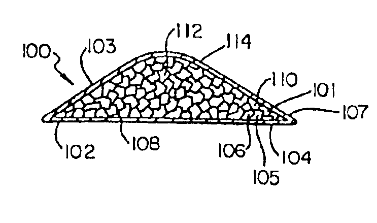
The mechanical energy is applied by inflating the balloon to which the tubular main body is adhered. Inflating the balloon radially expands and stretches the deformable, biodegradable material of the tubular main body. The stretching is of a magnitude to reorient molecules of one stent embodiment. The stretching is also of a magnitude to burst microcapsules contained in the biodegradable material of the

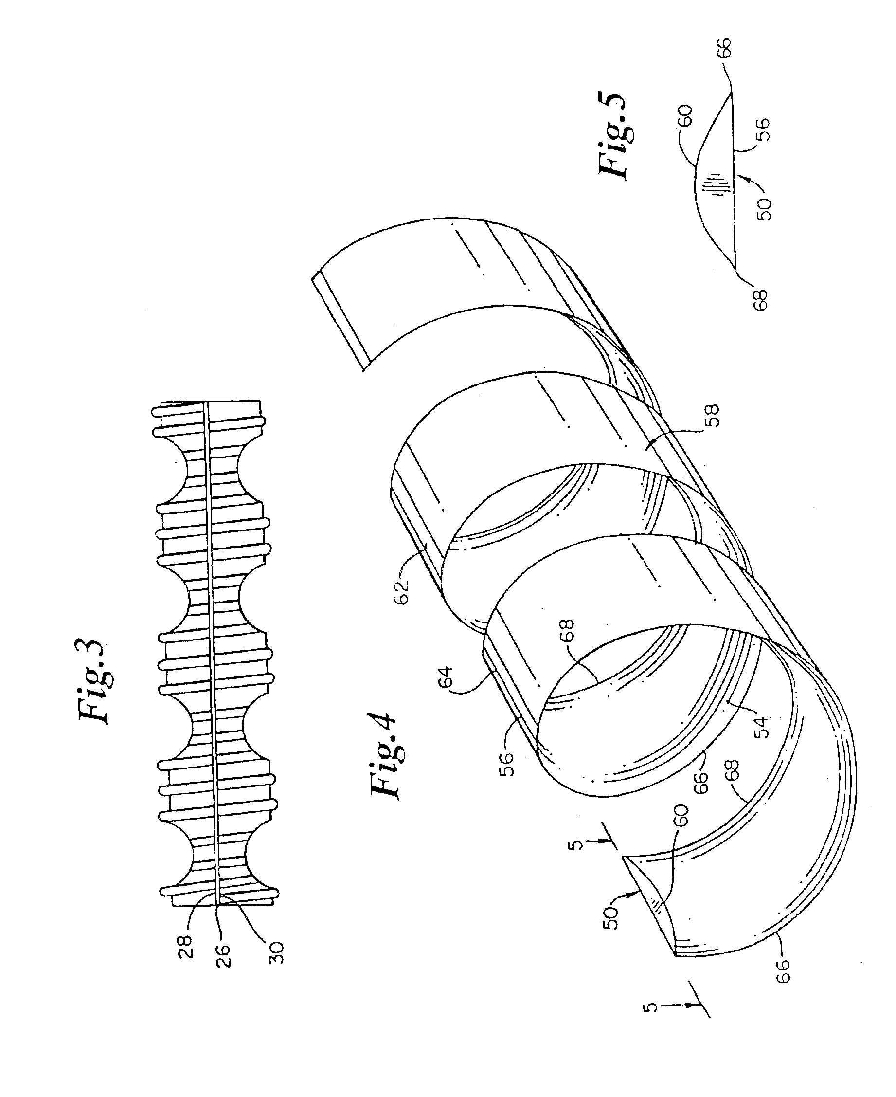
In one embodiment of the biodegradable coiled stent 50, the main body 58 is made from a single individual biodegradable material such as polylactic acid (pla). Preferably, the pla has a low degree of polymerization (dp).

In one other embodiment, the main body 58 is made from a plurality of individual, biodegradable materials arranged in layers. Each of the individual, biodegradable layers has distinct physical and chemical properties.

In one layered embodiment of the coiled stent 50, an inner layer contacting the fluid passing through the vessel lumen, is made of either polylactic acid,...


PUM

PropertyMeasurementUnit
Temperatureaaaaaaaaaa
Glass transition temperatureaaaaaaaaaa
Biodegradabilityaaaaaaaaaa

Abstract

A stent includes a main body of a generally tubular shape for insertion into a lumen of a vessel of a living being. The tubular main body includes a substantially biodegradable matrix having collagen IV and laminin that enclose voids within the matrix. The tubular main body also includes a biodegradable strengthening material in contact with the matrix to strengthen the matrix. The tubular main body is essentially saturated with drugs.

Description

BACKGROUND OF THE INVENTIONThis invention relates to a device for providing mechanical support and a uniform release of drugs to a vessel lumen of a living being.A variety of medical situations requires the use of a mechanism to expand and support a constricted vessel and to maintain an open passageway through the vessel. A few examples of such situations following angioplasty include holding a dissection in place, preventing closure during spasm, and preventing acute closure due to thrombosis. In these situations, devices, commonly known as stents, are useful to prevent stenosis of a dilated vessel, or to eliminate the danger of occlusion caused by “flaps” resulting from intimal tears that may be associated with angioplasty, or to hold two ends of a vessel in place.Stents have been made using materials of varied composition and conformation. McGreevy et al. U.S. Pat. Nos. 4,690,684 and 4,770,176, describe a meltable stent that is inserted into the interior of the ends of a blood ve...

Claims


Application Information

Patent Timeline
IPC IPC(8): A61F2/06A61L31/14A61L31/16A61F2/00A61F2/02A61F2/82A61F2/88
CPCA61F2/82A61L31/041A61L31/044A61L31/047A61L31/148A61L31/16A61F2/88C08L67/04Y10S623/901A61F2/958A61F2210/0004A61F2210/0023A61F2250/0067A61F2250/0068A61L2300/42A61L2300/604A61L2300/606A61L2300/622
Inventor BUSCEMI, PAUL J.STEJSKAL, ELIZABETH A.PALME, II, DONALD F.WANG, LIXIAO
Owner SCI MED LIFE SYST
Why Eureka
Try Eureka