Apparatus for passing stock into a headbox of a paper machine or equivalent

a technology of paper machine and headbox, which is applied in the direction of liquid degasification, separation processes, papermaking, etc., can solve the problems of increasing the disturbance, affecting the efficiency of the paper machine, and the degasification tank not having a constant pressure, so as to achieve a smaller process volume, reduce the disturbance, and reduce the effect of energy consumption

Inactive Publication Date: 2005-03-22
VALMET TECH INC
View PDF3 Cites 2 Cited by
  • Summary
  • Abstract
  • Description
  • Claims
  • Application Information

AI Technical Summary

Benefits of technology

In accordance with the invention, the deaeration tank can be accomplished without an overflow if it is in hydraulic connection with an overflow surface in the cellar. For example, the lock water part in a circulation water tank can act as an overflow surface if the deaeration tank is arranged to treat wire water in the short circulation. It is advisable to build the overflow so that it is wide. When short circulation dilutions, among other things, for the headbox feed and fan pumps are taken from a connecting pipe, the pressure of the short circulation remains constant, because it is determined by a stable overflow at normal pressure, in which there is no problem caused by bubbling of air. In controlling the vacuum in the deaeration tank, turbo blowers may be more suitable than vacuum pumps. The process is simpler than before, consumes less energy and requires a considerably smaller process volume. When the flow of wire water increases, the speeds in the cyclone and in the spray tubes of the deaeration tank increase, which increases deaeration capacity.

Problems solved by technology

However, the deaeration tank does not guarantee a constant pressure since, in the pressure conditions of the deaeration tank, air bubbles take a large part of its liquid volume.
The foaming of air bubbles in the deaeration tank is unstable.
The pressure control of the headbox attempts to maintain a uniform pressure in the approach pipe, but it affects the level of the surface in the deaeration tank, intensifying the disturbance.
Mere removal of the overflow from the deaeration tank is not enough because the pressure variation turns into consistency variation.

Method used


Image

  • Apparatus for passing stock into a headbox of a paper machine or equivalent
  • Apparatus for passing stock into a headbox of a paper machine or equivalent
  • Apparatus for passing stock into a headbox of a paper machine or equivalent

Examples


Embodiment Construction

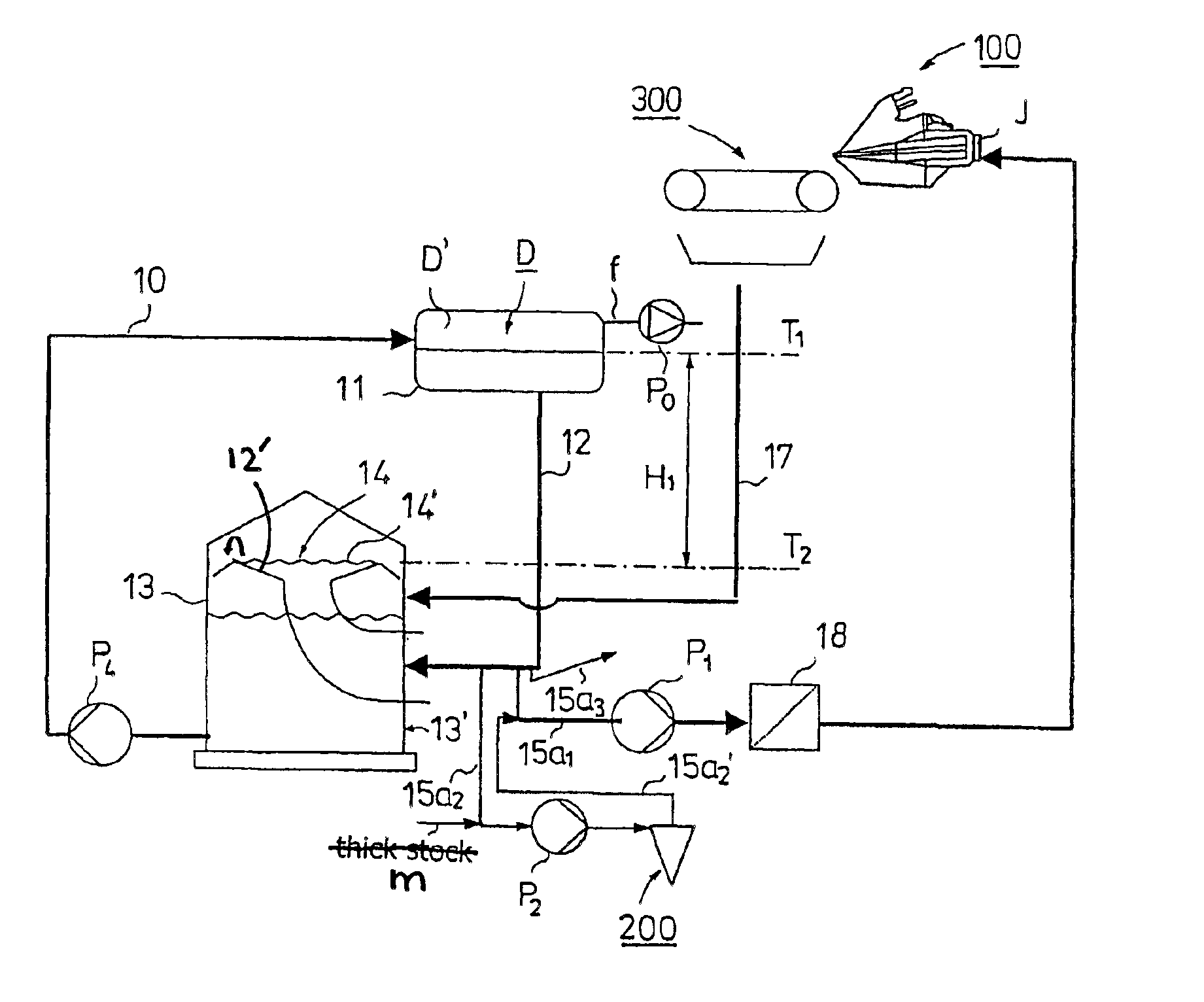
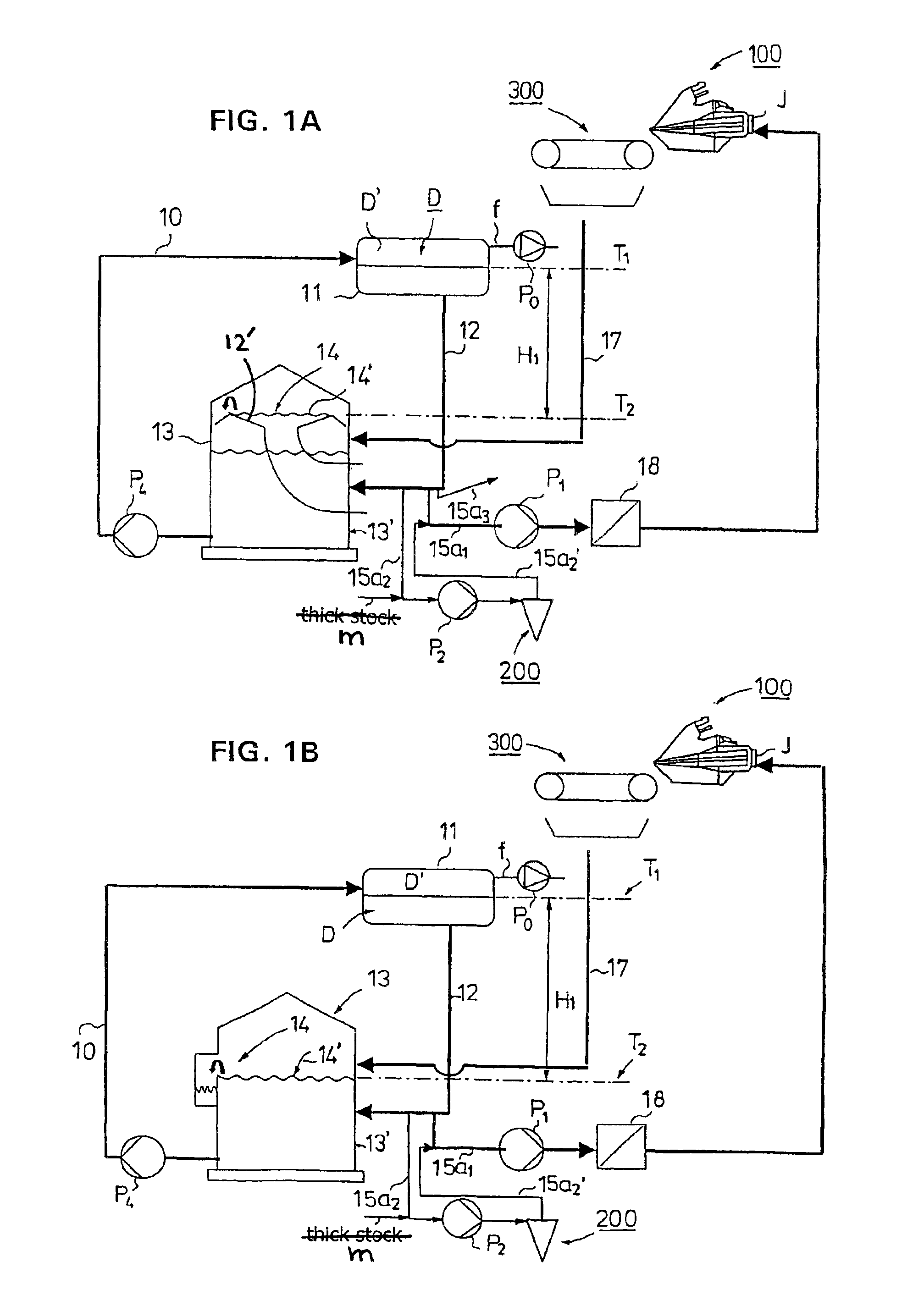
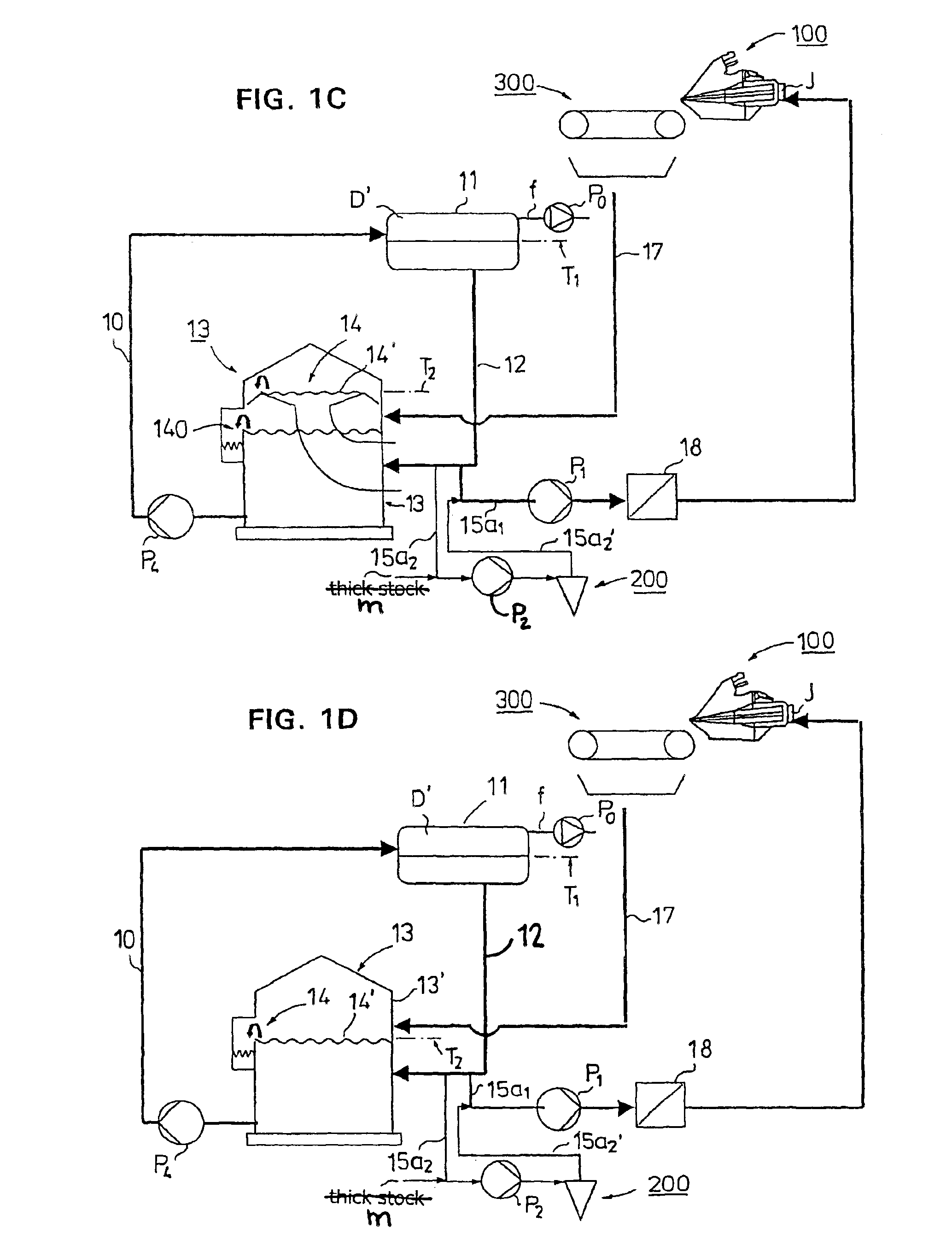
FIG. 1A shows a first advantageous embodiment of the invention which relates to a stock feed system of a headbox in a paper machine or equivalent and to its short circulation. Wire water is passed along a duct 10 into a deaeration tank 11, which has a discharge duct 12 for wire water from which air has been removed, and which discharge duct 12 comprises at its end an overflow 14, in which connection the height difference H1 between the level T2 of the overflow surface 14′ of said overflow and the surface T1 of the wire water in the deaeration tank 11 is in a range of 5 to 10 m. The deaeration tank 11 comprises for wire water an inside tank space D, which comprises a vacuum space D′ above the liquid, into which space vacuum is drawn through a duct f by means of a vacuum pump P0, an exhaust pump or another device and, at the same time, air is removed from the wire water. By the wire water is meant water that is removed from a paper web on the paper machine.

As shown in FIG. 1A, the dis...


PUM

PropertyMeasurementUnit
pressureaaaaaaaaaa
heightaaaaaaaaaa
diameteraaaaaaaaaa

Abstract

A vacuum pump (P0) provides vacuum to a paper machine deaeration tank (11) which has an inlet duct (10) through which the tank is supplied with wire water. A discharge duct (12) extends from the deaeration tank (11). There is an overflow (14) for the wire water in the discharge duct at the discharge end of the discharge duct (12). The overflow (14) of the discharge duct (12) is located below the deaeration tank (11) and opens to a free air space. The discharge duct (12) includes a branch duct (15a1) for a flow which is passed to the headbox (100).

Description

STATEMENTS AS TO RIGHTS TO INVENTIONS MADE UNDER FEDERALLYSPONSORED RESEARCH AND DEVELOPMENTNot applicable.BACKGROUND OF THE INVENTIONThe invention relates to an apparatus for passing stock to a headbox of a paper machine or equivalent.SUMMARY OF THE INVENTIONWhen a deaeration tank is situated between centrifugal cleaning and a headbox feed pump in the short circulation, it should act not only as a means of removing air but also as a pressure equalizer before the headbox feed pump. However, the deaeration tank does not guarantee a constant pressure since, in the pressure conditions of the deaeration tank, air bubbles take a large part of its liquid volume. For example, 5% of air takes 50% of the liquid volume at a pressure of 0.1 atm. The foaming of air bubbles in the deaeration tank is unstable. The overflow from the deaeration tank evens out the surface but it pays no attention to whether there is air or gas in the liquid space of the deaeration tank. For this reason, the pressure...

Claims


Application Information

Patent Timeline
Patent Type & Authority Patents(United States)
IPC IPC(8): D21D5/00D21F1/00D21D5/26D21F1/66
CPCD21F1/00D21D5/26
Inventor HIETANIEMI, MATTI
Owner VALMET TECH INC
Why Eureka
Try Eureka