
Device and method for determining intermittent short circuit

a technology of intermittent short circuit and determining device, which is applied in the direction of electrical equipment, emergency protective arrangement details, and semiconductor devices, can solve the problems of large amount of current continuously flowing, large prior art intermittent short circuit determining device, and high cost, and achieve the effect of detecting the occurrence of intermittent short circuit more accurately

Inactive Publication Date: 2005-03-22
PACIFIC ENGINEERING CORPORATION
View PDF6 Cites 59 Cited by
  • Summary
  • Abstract
  • Description
  • Claims
  • Application Information

AI Technical Summary

Benefits of technology

It is an object of the present invention to provide a device and method for detecting the occurrence of an intermittent short circuit more accurately.
A further object of the present invention is to provide a compact and inexpensive intermittent short circuit determining device.

Problems solved by technology

A dead short circuit causes a large amount of current to continuously flow in an electric circuit.
This makes the prior art intermittent short circuit determining devices large and expensive.

Method used


Image

  • Device and method for determining intermittent short circuit
  • Device and method for determining intermittent short circuit
  • Device and method for determining intermittent short circuit

Examples


first embodiment

the present invention may be changed as follows.

In step S5 of FIG. 4, if it is determined that the load current value Id is greater than the first current threshold value A1, the CPU 6 may proceed to step S18. In step S18, if it is determined that the first time period TA is less than or equal to the first reference time period T1, the CPU 6 may proceed to step S7.

In step S5 of FIG. 4, if it is determined that the load current value Id is greater than the first current threshold value A1, the CPU 6 may proceed to step S19. In this case, the steps S6, S7, S8, S9, S10, S11, S12, S13, S14, S15, and S18 are omitted.

The IC 16A may have only one comparator circuit. The IC 16A may also have more than three comparator circuits.

The first mode signal and the second mode signal may be formed of only the current flow permission signal and the current shutdown signal, respectively.

The current threshold value, the reference duty ratio, and the reference overcurrent number K1 are set as required. ...

second embodiment

(Second Embodiment)

FIG. 7 is a schematic circuit diagram of an intermittent short circuit determining device 90 according to a second embodiment of the present invention. The intermittent short circuit determining device 90 is embodied in an automobile intermittent short circuit determining device.

FIG. 8A is a plan view of the intermittent short circuit determining device 90 without molded material. FIG. 8B is a front view of the determining device 90. FIG. 8C is a right side view of the determining device 90. FIG. 9 is a right side view of the intermittent short circuit determining device 90.

In the second embodiment, as shown in FIG. 8D, a rectangular multi-layer insulating substrate 41 has a wide conductive pattern (hereinafter, referred to as the conductive terminal pattern) 42a. The conductive terminal pattern 42a has three branching conductors 43. The branching conductors 43 are connected to lands 44 (see FIG. 8A) through plated through holes (not shown), respectively. The land...


PUM


Abstract

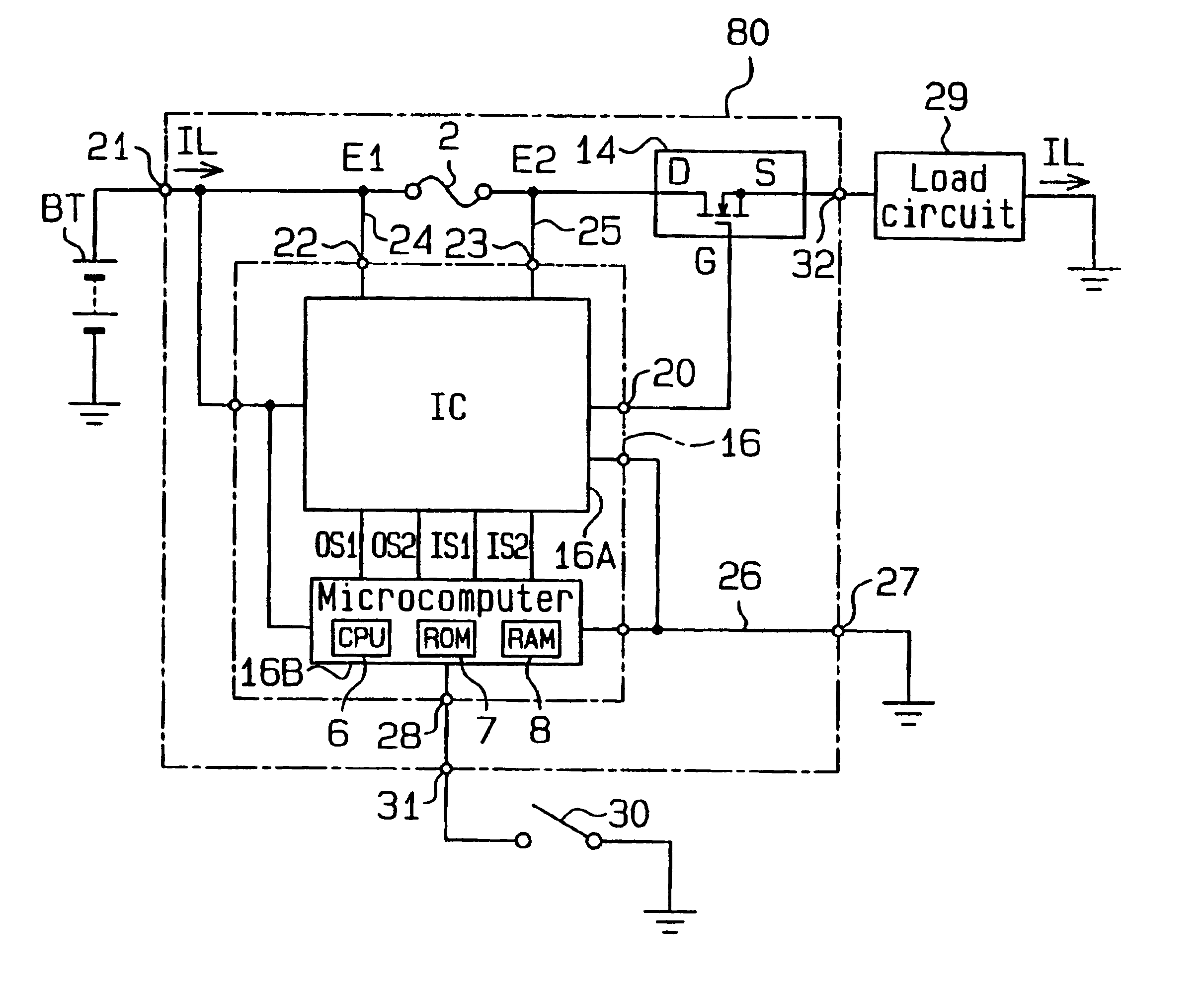
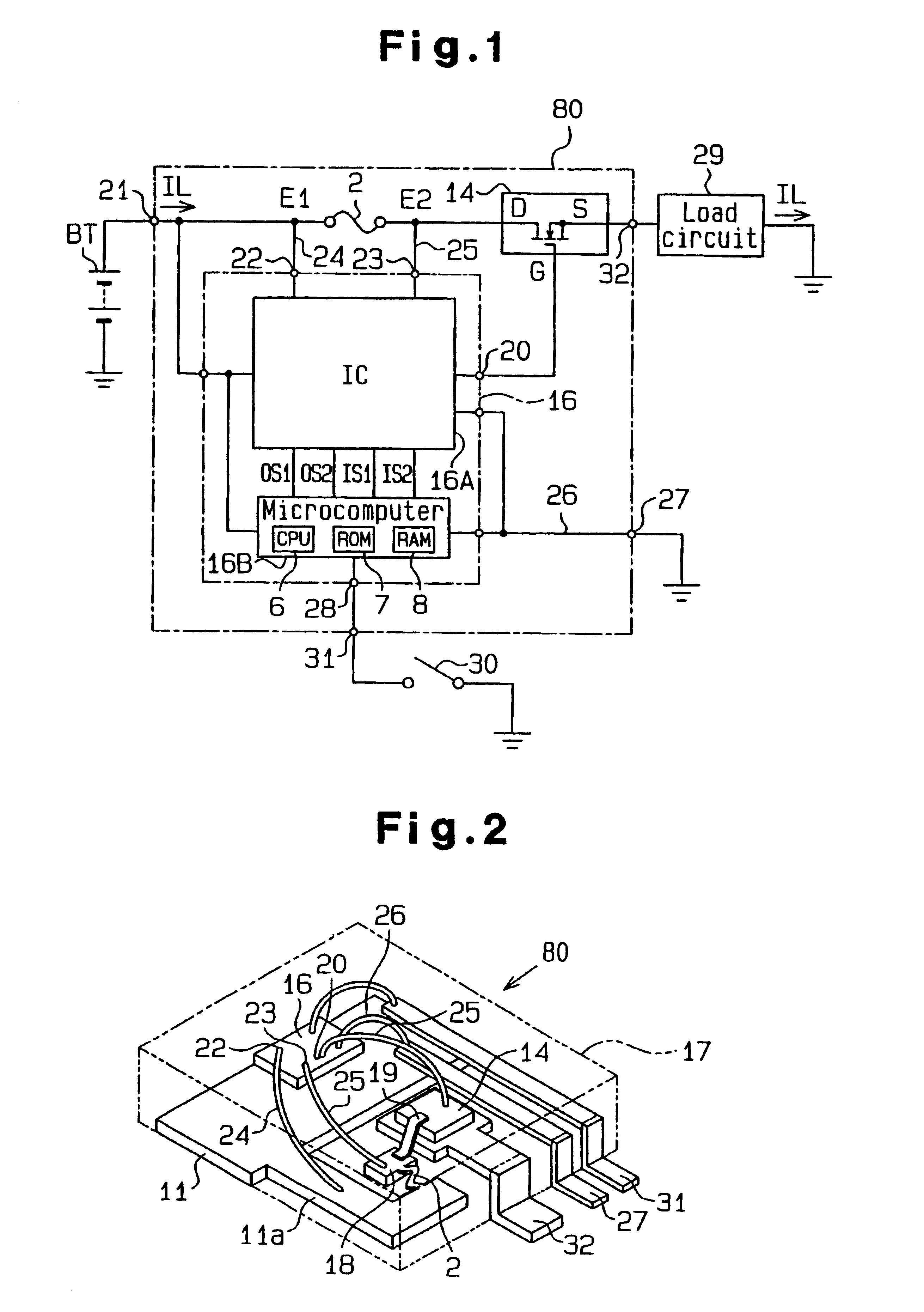
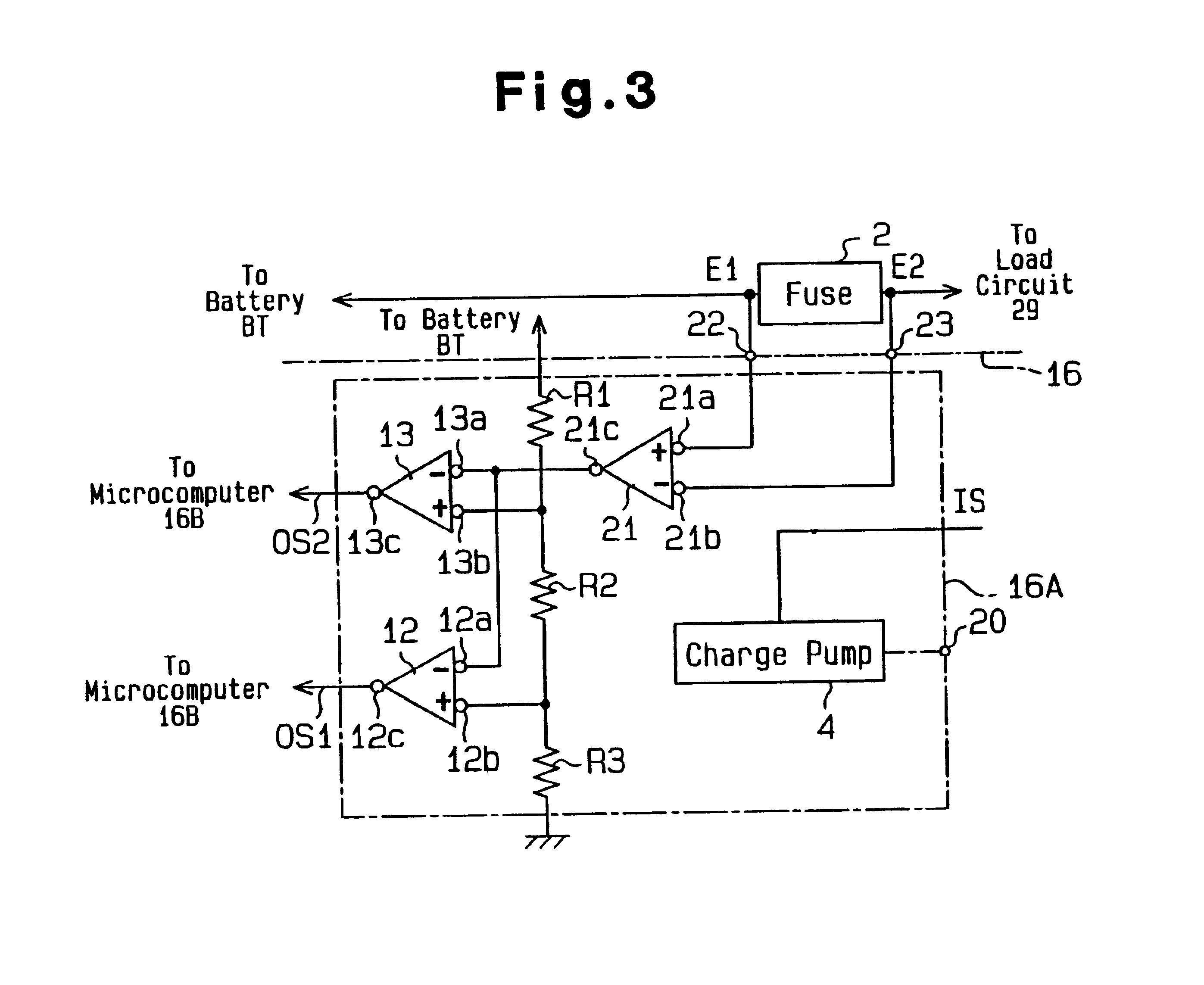
A miniaturized cost-saving intermittent short circuit determining device located between a power source and an electric load in a vehicle electric circuit. The determining device includes detecting means for detecting current flowing through the electric circuit, determining means for determining whether the current detected by the detecting means is an intermittent short circuit, and disconnecting means for disconnecting the electric circuit when the determining means judges that there is an abnormality. The determining means is connected to an external switch circuit, which selectively supplies and stops current to the electric load of the electric circuit. The determining means determines whether the external switch circuit is switched on or off, and switches the disconnecting means on or off according to the determination.

Description

BACKGROUND OF THE INVENTIONThe present invention relates to a device and method for determining the occurrence of an intermittent short circuit. More particularly, the present invention relates to an intermittent short circuit determining device and an intermittent short circuit determining method that detects overcurrent flowing through an electric circuit of an automobile.U.S. Pat. No. 4,023,264 describes a blade fuse installed in a fuse box of an automobile. Blade fuses, which are often used in electric circuits of automobiles, have a slow-burn characteristic. Due to the slow-burn characteristic, blade fuses are not melted by momentary excess currents but are melted by continuous excess currents that flow for a certain period of time.Blade fuses normally melt and break when a dead short circuit occurs but do not break when an intermittent short circuit occurs. A dead short circuit causes a large amount of current to continuously flow in an electric circuit. An intermittent short ...

Claims


Application Information

Patent Timeline
IPC IPC(8): H02H1/00H02H3/087H02H3/093
CPCH02H1/0015H02H3/087H02H3/0935H01L2224/48091H01L2924/13091H01L2224/4903H01L2224/49171H01L2924/3011H01L2224/48137H01L2924/00014H01L2924/00H01L2924/181H01L2224/45014H01L2224/49113H01L2924/00012
Inventor IWATA, TOSHINORIOHTA, MANABU
Owner PACIFIC ENGINEERING CORPORATION
Features
  • Generate Ideas
  • Intellectual Property
  • Life Sciences
  • Materials
  • Tech Scout
  • Unparalleled Data Quality
  • Higher Quality Content
  • 60% Fewer Hallucinations
Learn More