Passive balun FET mixer

a balun mixer and passive technology, applied in the field of mixer circuits, can solve the problems of affecting the quality of balun products,

Inactive Publication Date: 2005-03-22
SKYWORKS SOLUTIONS INC
View PDF13 Cites 74 Cited by
  • Summary
  • Abstract
  • Description
  • Claims
  • Application Information

AI Technical Summary

Benefits of technology

In accordance with one aspect of the invention, a FET mixer uses a balun having a primary and secondary, with the primary coupled to an RF signal input. The mixer also includes a pair of field effect transistors (FETs), wherein the gates are coupled to one another and to a local oscillator input. One of the source and the drain of the second of the two transistors is coupled at a node to one of the source and the drain of the other of the two transistors, and the node is coupled to ground. The other of the source and the drain of the first of the two transistors is coupled to one side of the secondary of the balun and the other of the source and the drain of the second of the two transistors is coupled to the other side of the secondary of the balun. An intermediate frequency signal output is coupled to a point in the circuit path between the first and second transistors.

Problems solved by technology

Additionally, the RF and IF signals are not isolated, resulting in possible distortion of these signals.
One problem with this design is that adding a centertap to a balun adds steps to the manufacturing process.
Another problem is that the IF output leads must cross over portions of the interleaved windings, making it susceptible to parasitic capacitance.

Method used


Image

  • Passive balun FET mixer
  • Passive balun FET mixer
  • Passive balun FET mixer

Examples


Embodiment Construction

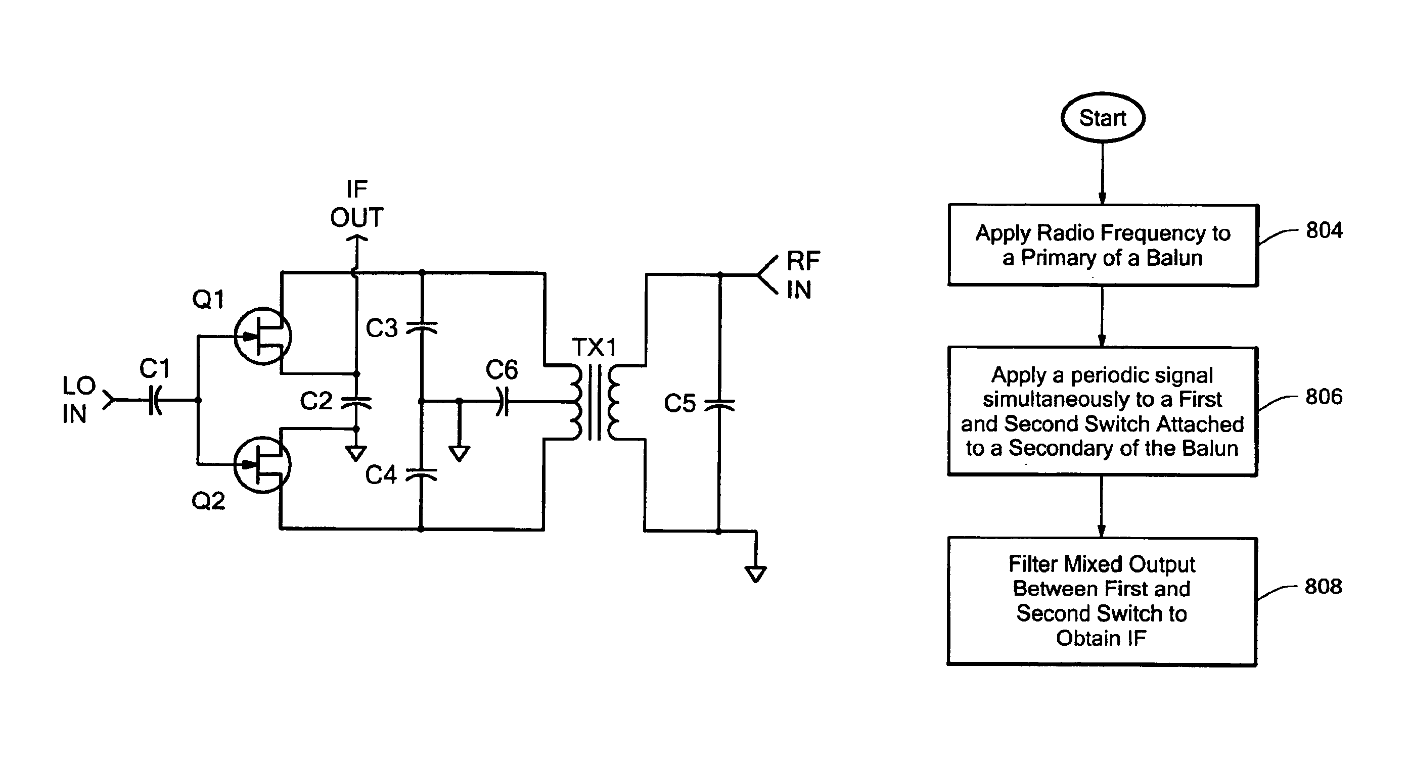
For the purposes of the description herein and the claims that follow it, unless the context otherwise requires, the term “Radio Frequency” (RF) means an electromagnetic signal at frequencies in the range extending from below 3 kilohertz to 300 gigahertz, which includes radio and television transmission. These frequencies are above audio signals and below the frequencies of visible light. The term “intermediate frequency” (IF) shall mean the frequency that an incoming signal is changed to. The term “local oscillator” (LO) shall mean a periodic signal. The term “balun” shall mean a transformer connected between a balanced source or load and an unbalanced source or load. A balanced line has two conductors, with equal currents in opposite directions. The unbalanced line has just one conductor; the current in it returns via a common ground or earth path.

FIG. 5 is a block diagram of the passive balun FET mixer in accordance with an embodiment of the present invention. Two switches 506, 5...


PUM


Abstract

A FET mixer uses a balun having a primary and secondary, with the primary coupled to an radio frequency signal input. The mixer also includes a pair of field effect transistors (FETs), wherein the gates are coupled to one another and to a local oscillator input. One of the source and the drain of the second of the two transistors is coupled at a node to one of the source and the drain of the other of the two transistors, and the node is coupled to ground. The other of the source and the drain of the first of the two transistors is coupled to one side of the secondary of the balun and the other of the source and the drain of the second of the two transistors is coupled to the other side of the secondary of the balun. An intermediate frequency signal output is coupled to a point in the circuit path between the first and second transistors.

Description

TECHNICAL FIELDThe present invention relates to mixer circuits, of the type having inputs for local oscillator (LO) and radio frequency (RF) signals and an intermediate frequency (IF) output, and in particular to mixer circuits using field effect transistors (FETs).BACKGROUND ARTMixers are contained in many radio transmitters, receivers, and other communication devices. Such mixers operate by combining an RF signal with LO, a periodic signal, producing a mixed output. This mixed output contains signals whose frequencies consist of either the sum or difference between RF and LO frequencies. By filtering the mixed output, an IF signal can be created whose frequency is either higher or lower than the original RF frequency.As a result of the desire to decrease the size of communication devices, mixer size must also be reduced. Double balanced diode mixers, widely used in the industry, are large. By utilizing FETs instead of diodes, and removing the multiple baluns, size can be reduced w...

Claims


Application Information

Patent Timeline
Patent Type & Authority Patents(United States)
IPC IPC(8): H03H7/00H03H11/02H03H11/32H03H7/42H03D7/12
CPCH03D7/125H03H11/32H03H7/42H03D2200/0023
Inventor PIRO, PHILIPCORNMAN, KEVIN
Owner SKYWORKS SOLUTIONS INC
Why Eureka
Try Eureka