
Pacemaker using measured intervals for mode switching

a pacemaker and mode switching technology, applied in the field of pacemakers, can solve the problems of reducing the work of the physician and reducing the risk of mistakes, and achieve the effect of reliable detection of atrial tachycardia

Inactive Publication Date: 2005-03-22
ST JUDE MEDICAL
View PDF11 Cites 15 Cited by
  • Summary
  • Abstract
  • Description
  • Claims
  • Application Information

AI Technical Summary

Benefits of technology

[0022]An object of the present invention is to provide a pacemaker operable in a tracking or a non-tracking mode of operation having an improved mode switching function for switching the pacemaker into the non-tracking mode of operation in response to the detection of an atrial tachycardia.
[0025]In the pacemaker according to the invention the necessary logic of the mode switching means is reduced compared to prior art designs. Due to its simplicity it will be more safe and easier to validate. Further, the number of programmable parameters will be few, which consequently reduces the work of the physician and reduces the risks of mistakes. The time from the start of tachycardia to the mode switch and back in the opposite direction is predictable and independent of the tachycardia rate, and can be selected in accordance with the patient's preferences.
[0028]In another advantageous embodiment of the Pacemaker according to the invention a unit is provided for changing the AV interval in order to uncover possible atrial events covered by the ventricular blanking period. In this way a more reliable detection of the atrial tachycardia is achieved and consequently a more reliable mode switch function.

Problems solved by technology

Further, the number of programmable parameters will be few, which consequently reduces the work of the physician and reduces the risks of mistakes.

Method used


Image

  • Pacemaker using measured intervals for mode switching
  • Pacemaker using measured intervals for mode switching
  • Pacemaker using measured intervals for mode switching

Examples


Embodiment Construction

n block form.

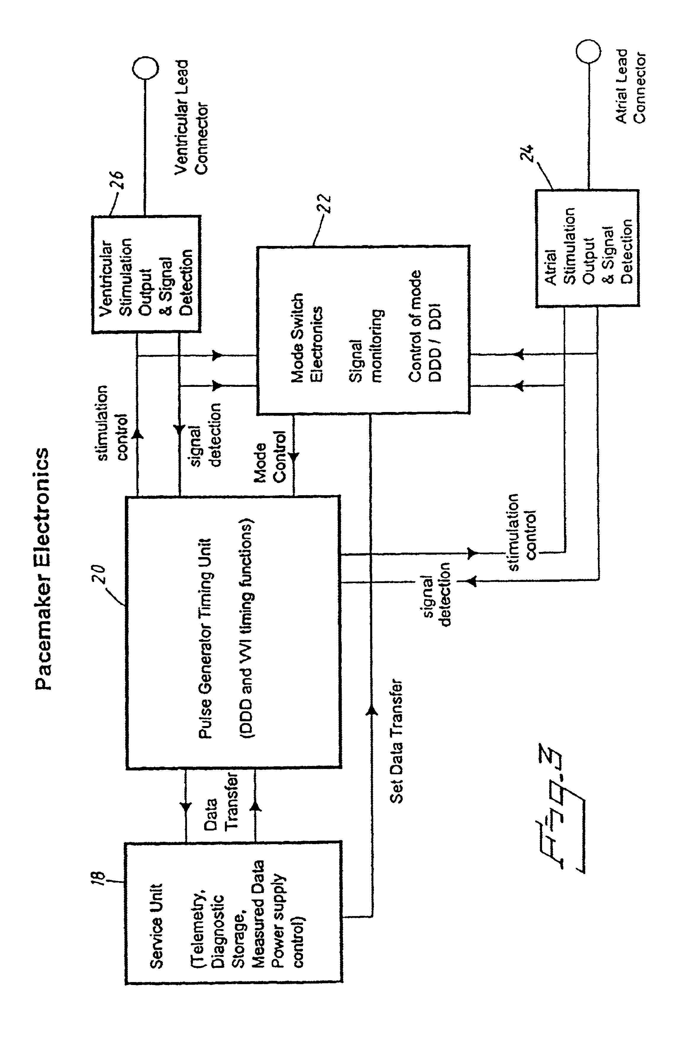
[0033]FIG. 4 illustrates the Mode Switch Electronics of the pacemaker according to the invention.

[0034]FIG. 5 shows a Generalized Counter Block for counting clock signals for time measurements in the pacemaker according to the invention.

[0035]FIG. 6 illustrates more in detail the Generalized Counter Block shown in FIG. 5.

[0036]FIG. 7 shows the counter in FIG. 6 more in detail.

[0037]FIG. 8 shows the Atrial Interval Counter in the form of a Generalized Counter Block.

[0038]FIG. 9 shows a Cardiac Event Interval Counter in the form of a Generalized Counter Block.

[0039]FIG. 10 shows more in detail the Automatic Mode Switch (AMS) Check Block of FIG. 4.

[0040]FIG. 11 shows more in detail the counter of the AMS Check Block shown in FIG. 10.

DESCRIPTION OF THE PREFERRED EMBODIMENTS

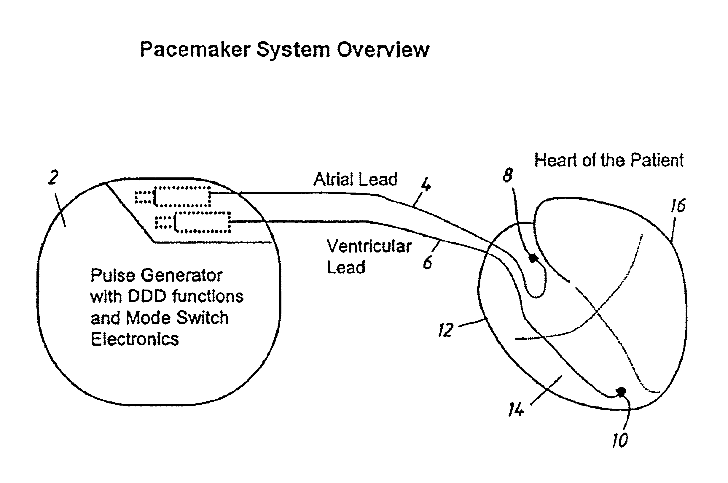
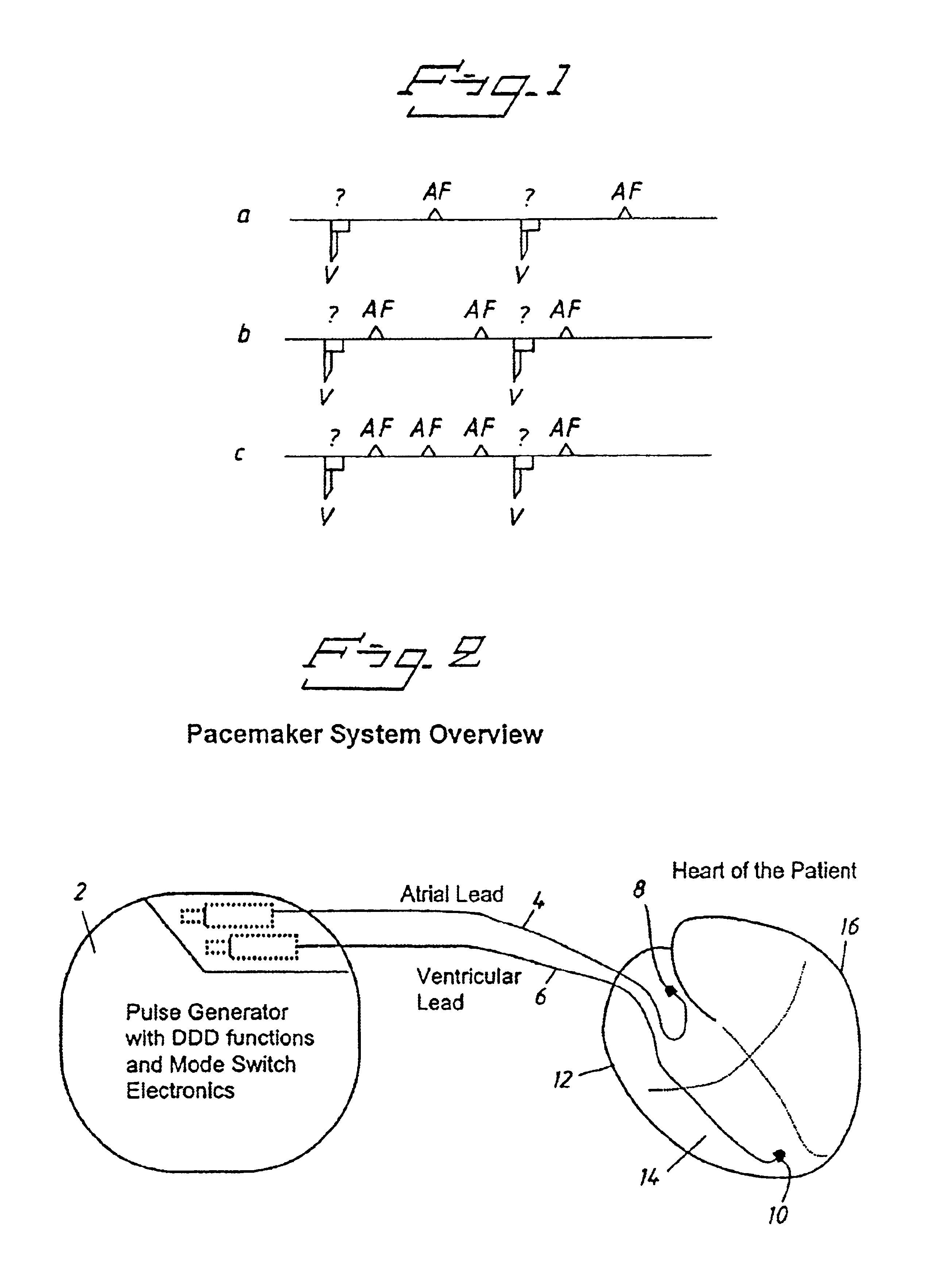
[0041]FIG. 2 shows an overview of the whole system of the pacemaker according to the invention including a pulse generator 2 with DDD functions and mode switch electronics for changing the mode of operati...


PUM


Abstract

A pacemaker is operable in a tracking and a non-tracking mode and has an automatic mode switching function for switching the pacemaker into the non-tracking mode of operation in response to the detection of atrial tachycardia. A comparator compares an atrial interval, between detected atrial events, with a predetermined atrial tachycardia limit value and records a tachycardia indication if the interval is less than the atrial tachycardia limit value. The mode switching unit switches the mode of operation to the non-tracking mode if the number of recorded tachycardia indications reaches a predetermined tachycardia count limit. Intervals between other cardiac events detected by the atrial detector or a ventricular detector also are supplied to the comparator wherein they are compared with the atrial tachycardia limit value. The recorded number of tachycardia indications is reduced by one if at least one of these additional intervals, during a pacemaker interval between two consecutive ventricular stimulations or between two consecutive R-wave detections, is longer than the tachycardia limit value.

Description

BACKGROUND OF THE INVENTION[0002]1. Field of the Invention[0003]The present invention relates to a pacemaker of the type that is operable in a tracking and a non-tracking mode and having an automatic mode switching function for switching the pacemaker into a non-tracking mode of operation in response to the detection of an atrial tachycardia, and including an atrial detector for detecting atrial events, a ventricular detector for detecting ventricular events, an atrial interval determining unit for determining the interval between consecutive atrial events, a comparator for comparing this interval with a predetermined atrial tachycardia limit value for recording a tachy indication if the interval is less than the atrial tachycardia limit value, and a mode switching unit for switching the mode of operation to the non-tracking mode when the number of recorded tachy indications reaches a predetermined tachy count limit.[0004]2. Description of the Prior Art[0005]Patients with paroxysmal...

Claims


Application Information

Patent Timeline
IPC IPC(8): A61B5/0464A61B5/0452A61N1/362A61B5/363
CPCA61N1/3622A61B5/0464A61B5/363
Inventor STRANDBERG, HANS
Owner ST JUDE MEDICAL
Learn More