Electric vehicle steering/drive control method, electric vehicle steering/drive control apparatus, and electric vehicle

a technology for electric vehicles and control methods, applied in the direction of steering initiations, underwater equipment, instruments, etc., can solve the problems of not being able to maneuver in this manner within the constraints of passageways, the passageways of such facilities are subject to vehicle passages, and the maneuverability of such facilities is not good enough to achieve the effect of reducing costs and simplifying vehicle operation

Inactive Publication Date: 2005-03-22
KANAZAWA INSTITUTE OF TECHNOLOGY
View PDF8 Cites 21 Cited by
  • Summary
  • Abstract
  • Description
  • Claims
  • Application Information

AI Technical Summary

Benefits of technology

Also, there may well be facilities having passageway constraints that are substantially uniform throughout the entire facility, but that cannot be satisfied by the wheel travel path pattern of conventional four-wheel-drive electric vehicles. It is also possible, however, that these constraints for the entire facility could be satisfied by one specific steering mode. In such cases, one need not necessarily provide a plurality of modes, but could instead specify a single mode that would meet the passageway constraints for the entire facility, thus simplifying vehicle operation while also reducing cost. For such a facility, the present invention can provide a steering / drive control method with only one particular steering mode that satisfies the conditions imposed by the passageway constraints of the facility. In such a case, the rotation of the steering and drive motors of the four wheels are controlled in accordance with the condition equation for that particular mode. One embodiment of the present invention also provides a steering / drive control system for executing one of the steering modes M1, M2, M3, M4 and M5, and an electric vehicle in which this control system is installed.

Problems solved by technology

The vehicle passageways in such facilities are subject to a variety of constraints that are unique to each facility.
Passageways in such facilities are normally not wide enough, nor do they have enough driving area at intersections, to give conventional vehicles adequate room to run straight, pass, and turn left and right without difficulty.
A survey of conventional electric cars, however, will reveal that none of them have the maneuverability to operate in this manner within the passageway constraints of the various types of facilities.
Accordingly, if one of these conventional electric cars in which the wheels always inscribe an inside wheel difference pattern were to be put into use—not on an ordinary street, but in one of these facilities in which passageway constraints are imposed—the vehicle would be found incapable of easily turning, changing its direction, or moving sideways.
Moreover, unless this control is exact, it can result in skidding or wheel-spinning during turns, and / or “toe-in” and “toe-out” when running straight.
Either condition can impede or prevent the forward travel of the vehicle.

Method used


Image

  • Electric vehicle steering/drive control method, electric vehicle steering/drive control apparatus, and electric vehicle
  • Electric vehicle steering/drive control method, electric vehicle steering/drive control apparatus, and electric vehicle
  • Electric vehicle steering/drive control method, electric vehicle steering/drive control apparatus, and electric vehicle

Examples


Embodiment Construction

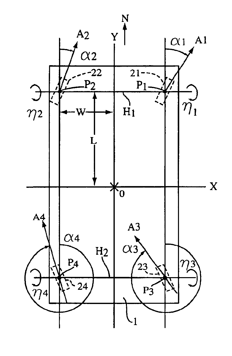
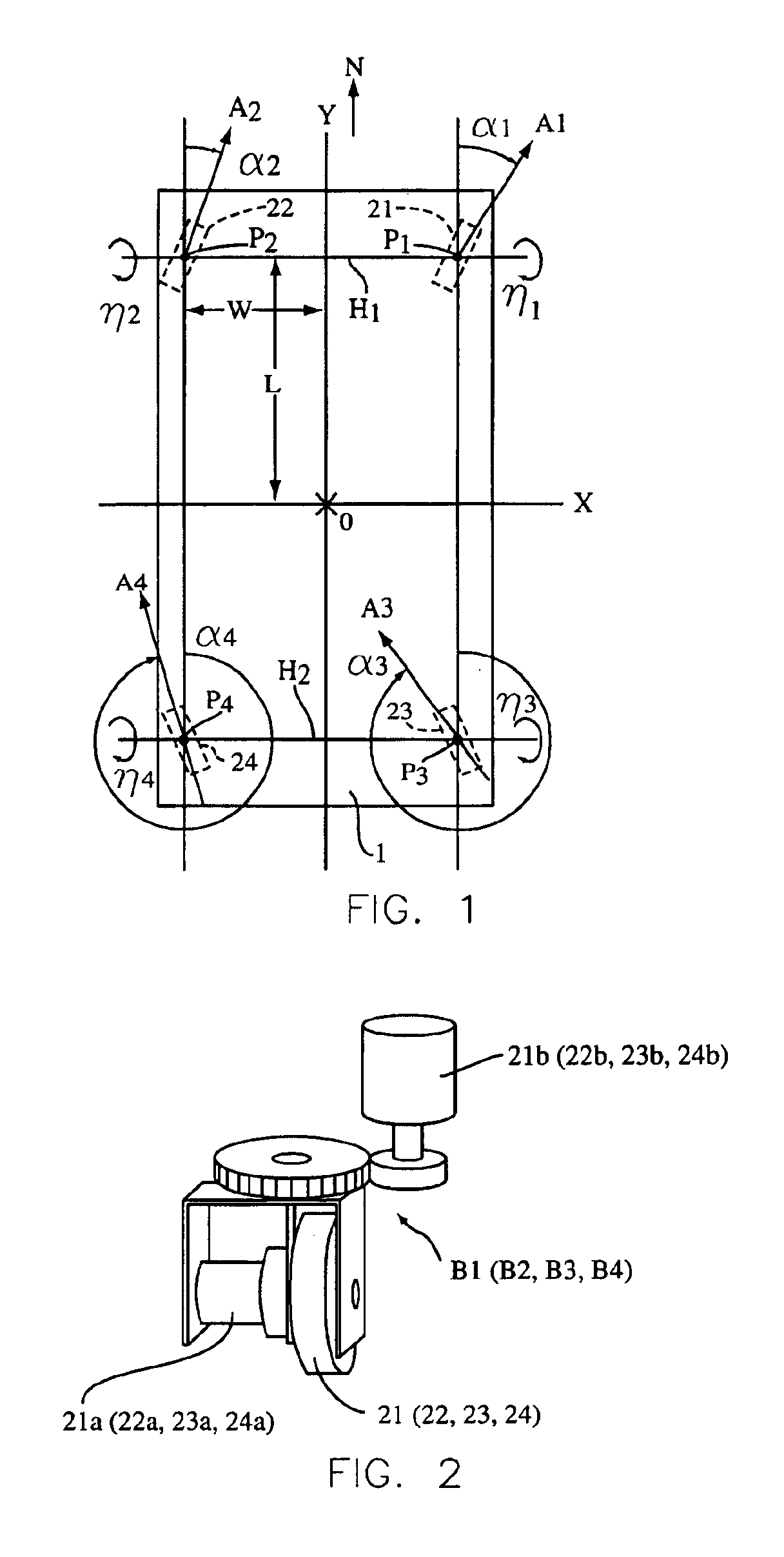
In the following paragraphs, the present invention will be described with reference to drawings showing an embodiment thereof. FIG. 1 is a plan view showing the basic configuration of a body base of the electric vehicle of the present invention. FIG. 2 is an oblique view of a steering / drive block that is installable on the body base of FIG. 1. Shown in FIG. 1 are an electric vehicle body base 1; points P1 and P2, indicating the locations at which the two front wheels, right and left, respectively, are installed on the under surface of the base body 1; and points P3 and P4, indicating the positions at which the two rear wheels, right and left, respectively, are installed on the under surface of the base body 1. Also shown are a right front wheel 21, a left front wheel 22, a right rear wheel 23, and a left rear wheel 24. An arrow N indicates the straight-forward direction of travel of the vehicle. Points P1, P2, P3, and P4, the locations of the wheels 21-24, lie at the intersections o...


PUM


Abstract

An electric vehicle steering/drive control method and apparatus having predetermined steering modes defining composite patterns of individual wheel travel paths, whereby the vehicle wheels are controlled independently. The steering modes are determined by different condition equations related to each composite pattern. A steering mode select signal is generated based on a mode selection by a vehicle driver. The steering mode select signal is received by a wheel steering angle computer and a wheel rotation speed computer. Based in part on the steering mode select signal, the wheel steering angle computer generates a signal that is received by a steering motor controller, which in turn controls motors that change the steering angle of the wheels. An actual angle sensor generates a signal based on the actual angle of the wheels and a steering angle comparator receives the actual angle sensor signal. In addition, to move the vehicle in a particular direction and at a particular speed, a speed and direction command signal is also generated based on driver input. This speed and direction command signal is received by a common signal rate of change suppression computer, which generates a signal received by the wheel steering angle computer and a wheel rotation speed computer. Then the wheel rotation speed computer generates a signal based on signals received from the common signal rate of change suppression computer and the steering angle comparator computer. A drive motor controller receives the wheel rotation speed signal and activates drive motors associated with each wheel, thereby causing the wheels to move rotationally.

Description

BACKGROUND OF THE INVENTION1. Field of the InventionThe present invention belongs to the field of steering and drive control systems used in electric, four-wheel-drive and four-wheel steering vehicles that have on-board battery power supplies, and that are operated at low speeds in various indoor and outdoor facilities other than public streets and highways, for example, hospitals and nursing homes, libraries, amusement parks, theme parks, sports and entertainment centers, offices, supply distribution bases, computer warehouses, large commercial facilities, etc. More specifically, the present invention is related to an electric vehicle steering / drive control method, a steering / drive system therefor, and an electric vehicle in which the steering and drive are controlled by this steering / drive system and method, wherein a variety of steering modes are provided and the driver selects from among these modes, the steering mode that is most appropriate for the instant driving conditions.2...

Claims


Application Information

Patent Timeline
Patent Type & Authority Patents(United States)
IPC IPC(8): B60L15/20B62D6/00B62D5/04B62D7/14
CPCB60L15/2036Y02T10/648Y02T10/7275Y02T10/646Y02T10/64Y02T10/72
Inventor OSHIMA, HIROYASUBABA, KAZUAKIIMAI, KATSUYAYAMADA, AKIHIRO
Owner KANAZAWA INSTITUTE OF TECHNOLOGY
Why Eureka
Try Eureka