Smart connector patch panel

a patch panel and connector technology, applied in the field of data acquisition, can solve the problems of amplifying the shorting of strain gages to determine the proper connection of strain gages, and requiring significant schedule time and labor

Inactive Publication Date: 2005-03-22
THE BOEING CO
View PDF2 Cites 80 Cited by
  • Summary
  • Abstract
  • Description
  • Claims
  • Application Information

AI Technical Summary

Benefits of technology

According to a preferred embodiment of the present invention a system is provided to remotely collect test setup data from a mobile platform. A platform can range from one strain gage on a simple test coupon, to several hundred strain gages on a component test, or to several thousand strain gages...

Problems solved by technology

This end-to-end verification requires significant amounts of schedule time and labor during the test critical path.
The disadvantage of individually reading labels on cables, de-mating or shorting connectors, or shorting strain gages to determine proper connec...

Method used


Image

  • Smart connector patch panel
  • Smart connector patch panel
  • Smart connector patch panel

Examples


Embodiment Construction

The following description of the preferred embodiment(s) is merely exemplary in nature and is in no way intended to limit the invention, its application, or uses.

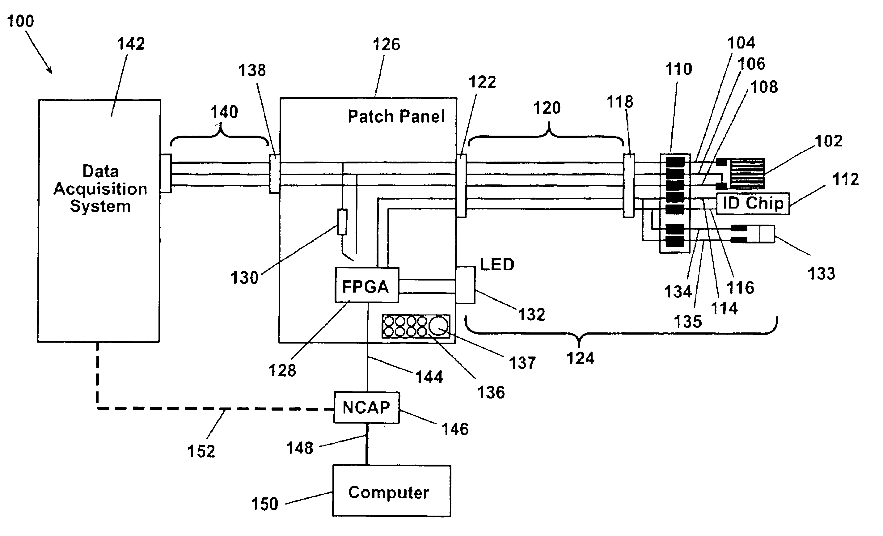
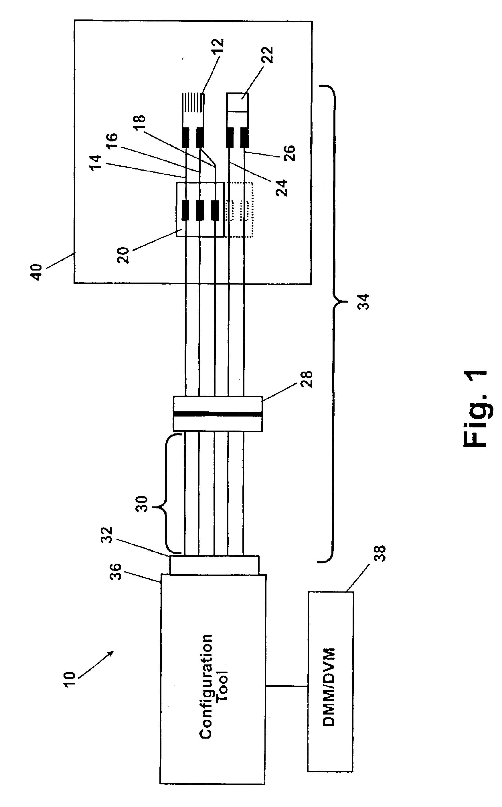
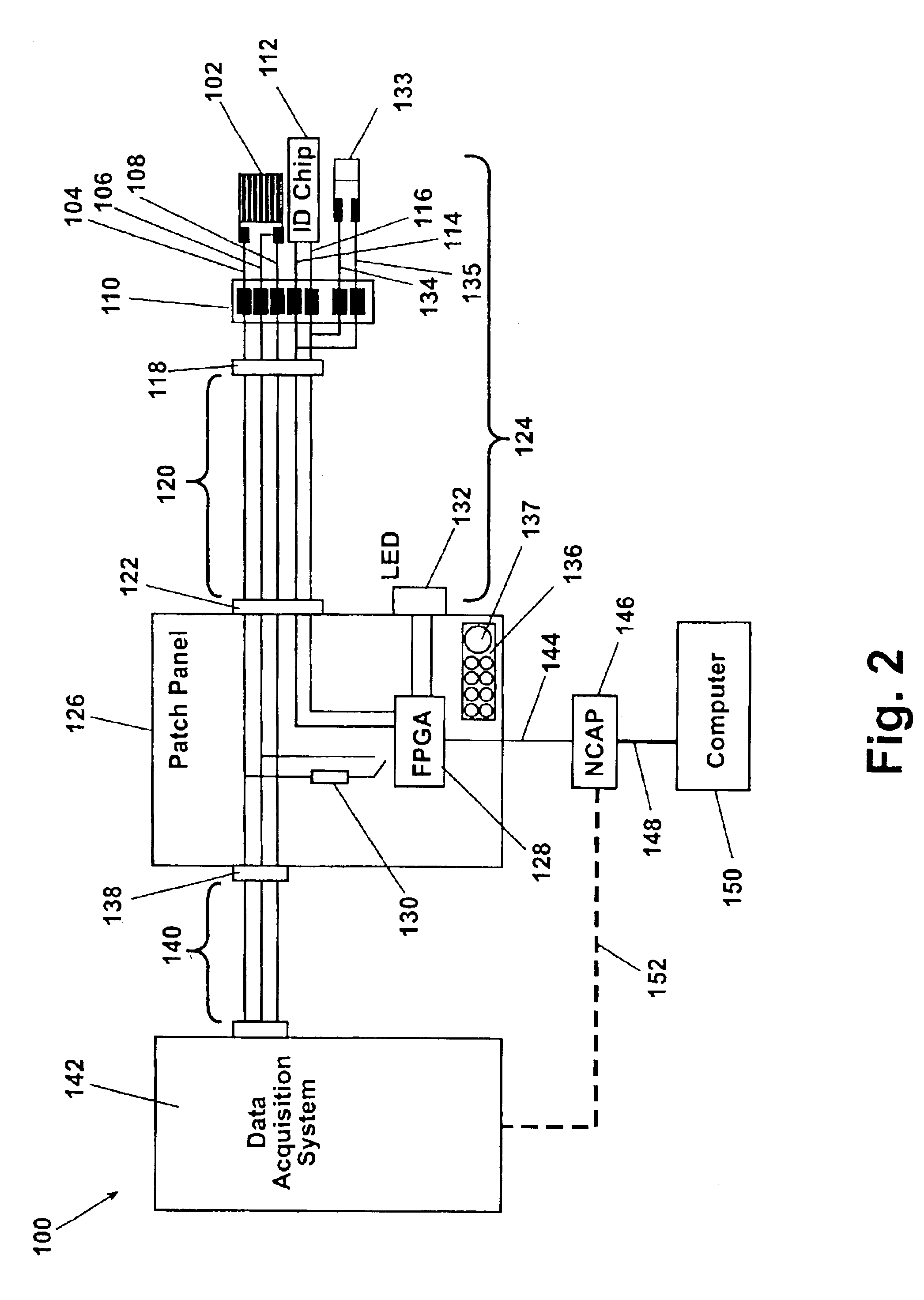
Referring to FIG. 1, a sensor system 10 includes at least one strain gage 12 having a first lead 14, a second lead 16, and a third lead 18 each connected to a common terminal strip 20 (e.g., by soldering). The first lead 14 typically provides current to the strain gage 12. The second lead 16 is the return path for the current from the strain gage 12. The third lead 18 from the strain gage 12 is a signal lead normally fed to signal conditioning equipment (not shown), where the output is read as the strain gage 12 output. Each strain gage 12 is provided with an associated identification chip 22. The identification chip 22 is known and includes a multi-bit, unique identification code or number which is assigned to the identification chip 22 when it is constructed. The unique identification code assigned to the identification c...


PUM


Abstract

A system remotely collects test data from a test platform using platform attached sensors. Identification chips, each having a unique identification code, are each paired with an associated sensor to form sensor/chip pairs. At least one patch panel having a plurality of connections is positioned approximate to the platform. Connections are communicatively linked to each of the sensor/chip pairs. A computer system is communicatively linked to additional patch panel connections. The identification of selected sensors is queried by a computer command to the patch panels, and a group of sensors for a given test is identified and selected. Test data from each of the selected sensors is transferred through the patch panels to the computer system for collation and generation of a test setup compatible with a data acquisition system. Test setup information is downloaded to the data acquisition system in preparation for the next test.

Description

FIELD OF THE INVENTIONThe present invention relates in general to data acquisition and more specifically to a system and method to selectively identify and collect data from one or more specific test devices.BACKGROUND OF THE INVENTIONTest laboratories need to monitor several hundred (up to several thousand) strain gages and other test devices during structural qualification of aircraft, launch vehicles, or other types of structures. A data acquisition system is commonly used to collect and collate test data. To ensure proper data collection, the connection between each strain gage or device and the data acquisition system needs to be verified. This end-to-end verification requires significant amounts of schedule time and labor during the test critical path. The verification typically involves reading labels on strain gage cables, de-mating or shorting connectors, or shorting strain gages and observing information in the data acquisition system.The disadvantage of individually readi...

Claims


Application Information

Patent Timeline
IPC IPC(8): G01B7/16G06F19/00H04L12/26
CPCH04L43/50H04L12/2697
Inventor WALLACE, JAMES P.MILLEN, ROBERT E.BOHR, GERARD V.JUELFS, RODNEY A.
Owner THE BOEING CO
Why Eureka
Try Eureka