Flying insect trap

a technology for flying insects and traps, which is applied in the field of insect traps, can solve the problems of negative effect on the overall catch effectiveness of traps and insects cannot directly perceive light sources, etc., and achieve the effects of reducing parts and inventory, increasing access, and increasing effectiveness

Inactive Publication Date: 2005-03-29
PARACLIPSE SYST
View PDF5 Cites 54 Cited by
  • Summary
  • Abstract
  • Description
  • Claims
  • Application Information

AI Technical Summary

Benefits of technology

Thus, the present invention provides two separate UV lamps arranged generally in the same horizontal plane and spaced slightly laterally from one another. The lamps are mounted in an elongated housing which has upright sidewalls and a base, but which is provided with open grills adjacent the horizontal plane in which the UV lamps are mounted so that the lamps can be viewed directly in a range of elevations extending from slightly below the horizontal plane of the lamps to a region well above the lamps. Moreover, the shape of the housing in side profile is such that it curves upwardly and inwardly of the UV lamps, as one proceeds from the level of the UV lamps upward. This increases the access of the insects to the UV lamps, not only by sight, but by ingress, from an angle slightly below the horizontal to approximately 80° above the UV lamps. Access is provided on both sides of the housing to increase the effectiveness even more. In addition, curved reflective surfaces are placed at an incline to the center of the unit and above the UV lamps to project an image of the UV lamps outwardly and downwardly so that it can be perceived from most regions in a room and extends the viewing angles well below the horizontal. Thus, an insect in front of the unit sees not only the UV lamp directly, but the image of the lamp, and this occurs on both sides of the unit.
Furthermore, the insect trapping medium, which is commercially available, has a sticky or tacky surface impregnated with the attractants described above. The medium is stored in a cartridge until use. The trapped insects become encapsulated in a take-up section, while simultaneously a fresh adhesive surface is automatically advanced from a source spool. U.S. Pat. No. 5,651,211 teaches the use of a cartridge for housing the trapping medium in a roll and dispensing it for usage under timed motor power. The present invention improves such a cartridge design by housing a roll of trapping medium in a cartridge made of two mating sections which are preferably identical and interchangeable to reduce parts and inventory. The two housing sections couple together to form a substantially closed container encompassing the trapping medium either for storage when the medium has not been used, or for disposal when the trapping medium is filled with insects.

Problems solved by technology

Of course, the insects cannot directly perceive the light source unless the insect is at a sufficiently high altitude.
This is believed to have a negative effect on the overall catch effectiveness of the trap since insects are believed to be attracted to the UV light source by sensing light emanating from the source, just as insects are attracted to windows because they sense the incoming light radiated from the sun.

Method used


Image

  • Flying insect trap
  • Flying insect trap
  • Flying insect trap

Examples


Embodiment Construction

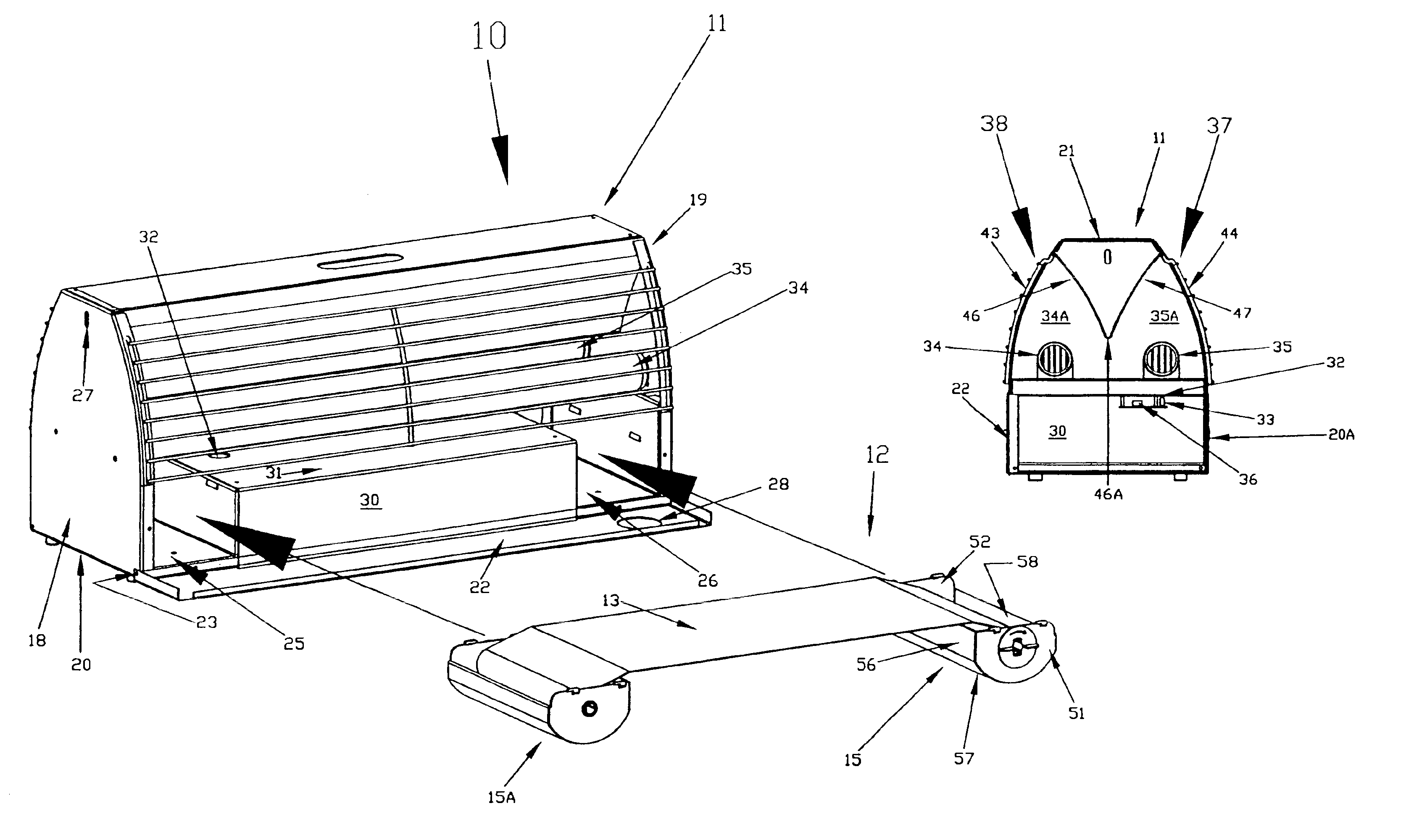
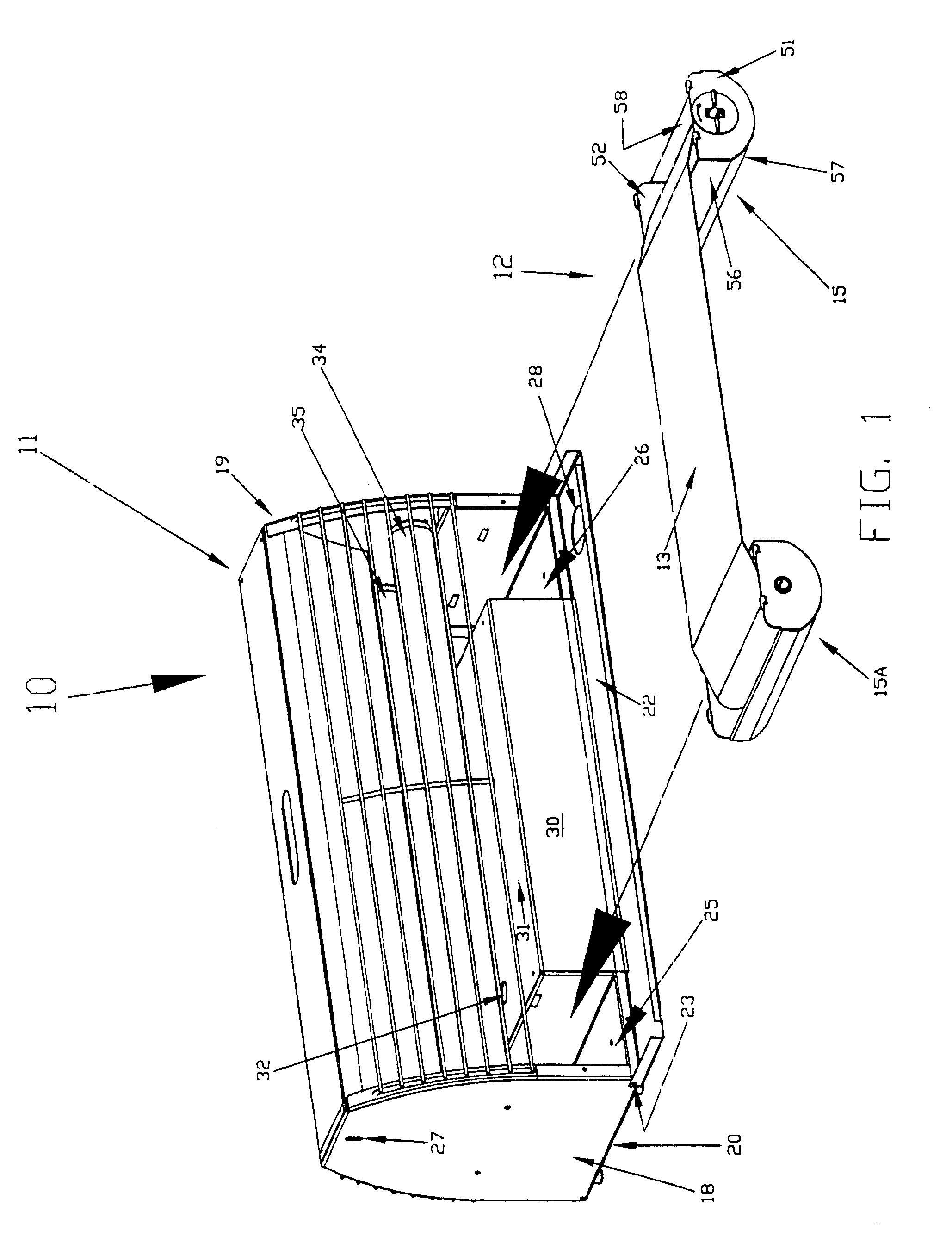
Turning first to FIG. 1, reference numeral 10 generally designates a trap for flying insects. The trap 10 comprises a housing generally designated 11 and a replaceable cartridge 12 for housing and supplying trapping medium shown in the form of an elongated web and designated 13 in FIG. 1. The cartridge 12 is seen in FIG. 1 with first and second complimentary and similar sections 15, 15A spread apart for insertion into the trap 10, as will be described. In FIG. 3, the cartridge sections 15, 15A have been disconnected from each other, and if the cartridge sections are spread further apart, the exposed surface of the trapping medium 13 will, of course, be increased. A feature of the invention is that the same cartridge design may be used for different size traps having different lengths of exposed trapping medium, as persons skilled in the art will appreciate.

Returning now to FIG. 1, the housing 11 is elongated laterally to accommodate two fluorescent lamps, to be described. The housin...


PUM


Abstract

A flying inspect trap includes large, multi-directional, oppositely facing ingress openings to elongated chambers housing UV lamps emitting insect attractant light. A disposable cartridge has two sections which mate together to form a container for a roll of adhesive trapping medium. The cartridge sections are opened and spread apart to fit beneath the UV lamps. A motor indexes the adhesive medium so that some unused portion is always available for trapping insects until the roll is exhausted. The spent roll is then rolled into one cartridge section externally; and the two cartridge sections are coupled together to encase the spent roll for disposal.

Description

FIELD OF THE INVENTIONThe present invention relates to insect traps, and more particularly to traps for flying insects which use ultraviolet (UV) light to draw the insects into the trap where they are immobilized on adhesive-coated boards, paper or other medium.BACKGROUND OF THE INVENTIONThe use of ultraviolet light to attract insects in a localized area and then to immobilize the insects on an adhesive medium or “glue board” is known. Further, it is known to provide food scents and pheromones to attract flies and other insects into the interior of the trap and onto the adhesive medium. One prior trap disclosed in U.S. Pat. No. 5,651,211, is intended to be mounted on a wall and have a decorative cover so that occupants of the room cannot normally see the UV lamps directly. Such decorative traps have application primarily in eating areas of restaurants or the like so that the UV lamps provide indirect lighting on an adjacent wall, but the lamps themselves are not directly visible at ...

Claims


Application Information

Patent Timeline
Patent Type & Authority Patents(United States)
IPC IPC(8): A01M1/00A01M1/14
CPCA01M1/145A01M2200/012
Inventor LAMBERT, C. RONALDSINCLAIR, KEVIN D.TAYLOR, LARRY R.
Owner PARACLIPSE SYST
Why Eureka
Try Eureka