Mold vent

Inactive Publication Date: 2005-03-29
THE GOODYEAR TIRE & RUBBER CO
View PDF16 Cites 28 Cited by
  • Summary
  • Abstract
  • Description
  • Claims
  • Application Information

AI Technical Summary

Benefits of technology

According to a further aspect of the invention, a mold with improved venting is provided having a mold cavity defined by a mold wall; a vent main body received within the mold wall; a viscous material contained within a portion of the vent main body; a vent valve member d

Problems solved by technology

Such plugs of rubber detract from the visual appeal of the molded tire and are usually removed by trimming.
A trimming operation, however, is time consuming and undesirably adds to the cost of the finished tire.
Another problem frequently encountered is that such plugs of rubber may break off when the tire is being extracted from the mold, thus blocking the vent hole.
A blocked vent hole may not be immediately apparent and can cause subsequent poor quality moldings.
While working well, certain problems remain unsolved by s

Method used


Image

  • Mold vent
  • Mold vent
  • Mold vent

Examples


Embodiment Construction

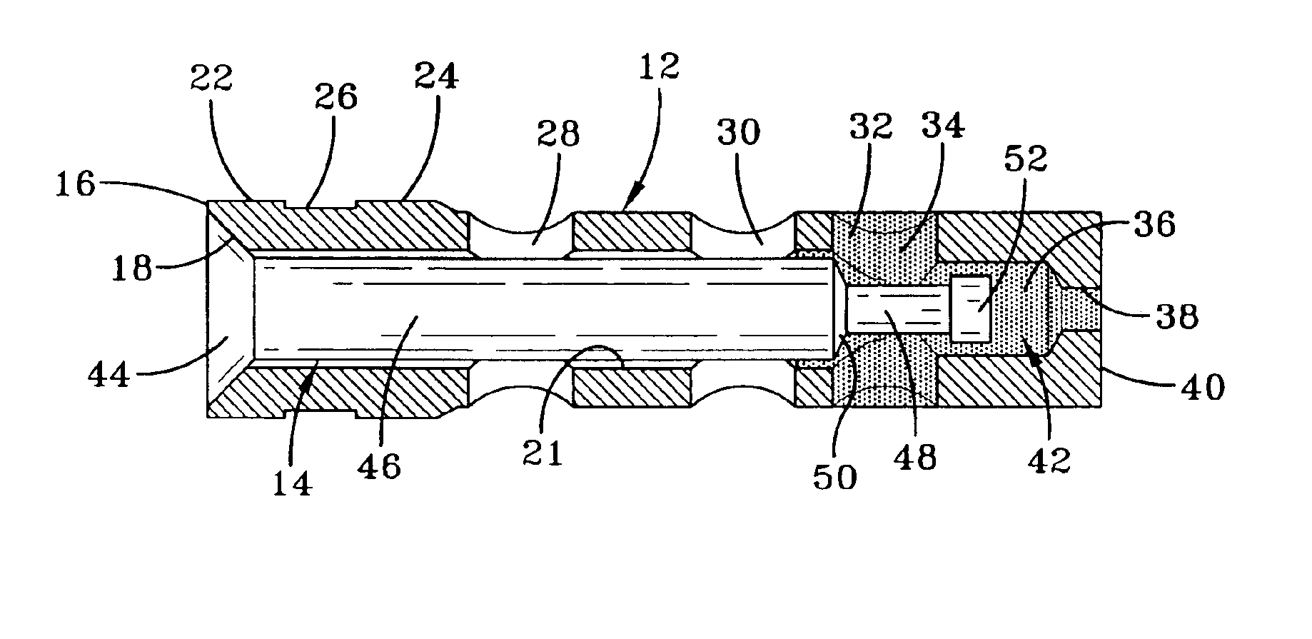
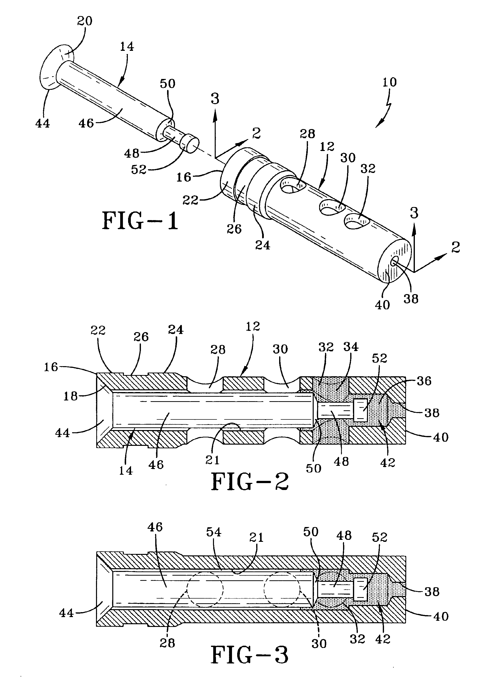
Referring first to FIGS. 1 and 2, one embodiment of the subject invention is shown to comprise a mold vent 10 for disposition within a mold wall region. The vent assembly 10 includes a vent main body 12 and a vent closure member 14 (interchangeably referred to herein as “valve member”). The vent main body 12 is generally a tubular structure or sleeve open at both ends to provide an air escape passage through the interior of the main body. At the upper end 16 of the vent main body 12, representing the end disposed at the molding surface, there is an internal conical seat 18. A complementary external conical-shaped vent closure face 20 is disposed on the valve member 14. Closure of the valve occurs when the complementary conical-shaped surfaces of the closure face 20 and the vent seat 18 are brought together by downward movement of the valve member 14 within the main body 12. While a conical seat is preferred, other alternative seat variations known in the art are intended to be withi...


PUM

PropertyMeasurementUnit
Flow rateaaaaaaaaaa
Viscosityaaaaaaaaaa
Mold temperatureaaaaaaaaaa

Abstract

A vent for a mold having a mold cavity comprises a valve member housed within a main body sleeve and reciprocally moveable therein in an axial direction between open and closed positions. The sleeve is mounted within a mold wall and contains an expansion agent such as silicon. An increase in mold temperature causes the expansion agent to expand and move the valve member from the closed position into the open position. An external annular groove is provided within the sleeve to receive displaced mold wall material as the sleeve is press inserted into the mold wall. A tight fit of the sleeve within the mold wall results. The sleeve and valve are configured to allow air to escape in the open position. The valve member is moved to the closed position by material within the mold cavity pressing against the valve member.

Description

FIELD OF THE INVENTIONThe present invention relates generally to vents for molds used in forming molded products and particularly but not exclusively to vents for tire molds.BACKGROUND OF THE INVENTIONIn molding rubber articles such as tires, the initial heating of the tire surface in contact with the hot mold rubber so that under the influence of internal molding pressure local rubber flow occurs. Venting is required to allow pockets of air which may become trapped between the green tire carcass and the hot mold to escape so that every part of the curing tire surface contacts the mold and the tire is thus vulcanized with a perfect impression of the mold detail.Variously configured mold vents have thus been proposed and used to accomplish the above-stated objective. One approach is in the use of small diameter holes drilled through a mold wall normal to the interior surface. Another common approach is the use of “insert vents” that comprise small bore tubes introduced through the mo...

Claims


Application Information

Patent Timeline
IPC IPC(8): B29C33/10B29D30/06B29C33/02B29D30/08B29L30/00
CPCB29C33/10B29D30/0606B29D30/0662B29L2030/00B29D2030/0617B29D30/08
Inventor CUNY, ANDRESCHMIT, GERARDNOWAK, ERICGIERES, GEORGES HUBERT HENRI
Owner THE GOODYEAR TIRE & RUBBER CO
Why Eureka
Try Eureka