Multi-part piston construction for a brake caliper of a disk brake

Active Publication Date: 2011-06-09
CONTINENTAL TEVES AG & CO OHG
View PDF20 Cites 21 Cited by
  • Summary
  • Abstract
  • Description
  • Claims
  • Application Information

AI Technical Summary

Benefits of technology

[0013]A recess in the pressure piece may receive a shoulder. For i

Problems solved by technology

Furthermore, known arrangements lack an adaptation to electromechanically actuatable brake actuator systems wherein a parking brake device acts on the brake piston by means of a transmission, the transmission converting a rotary motion of an actuator system into a translational motion, causing an actuation of the brake piston in order to execute parking brake operations and holding the brake piston in th

Method used


Image

  • Multi-part piston construction for a brake caliper of a disk brake
  • Multi-part piston construction for a brake caliper of a disk brake
  • Multi-part piston construction for a brake caliper of a disk brake

Examples


Embodiment Construction

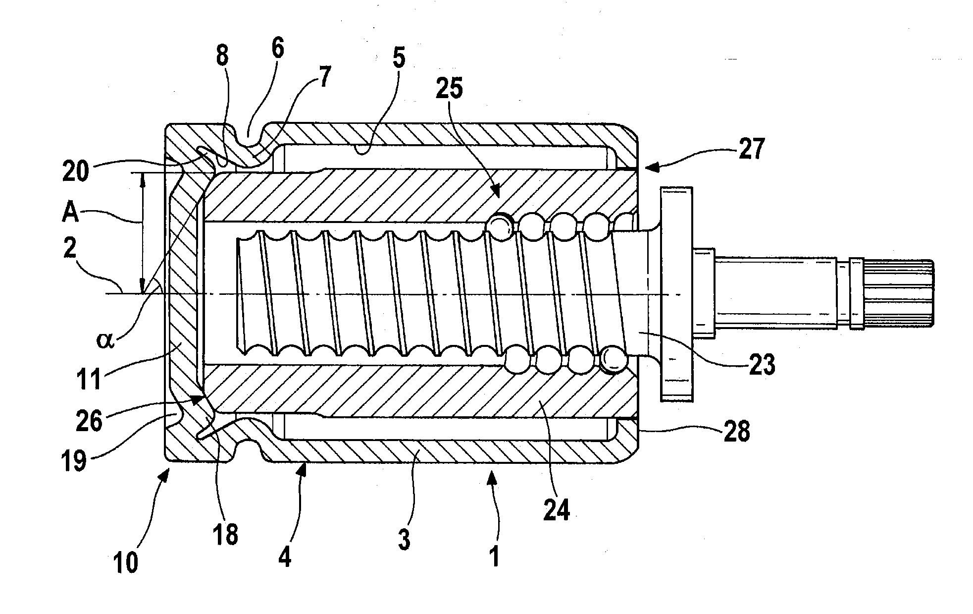
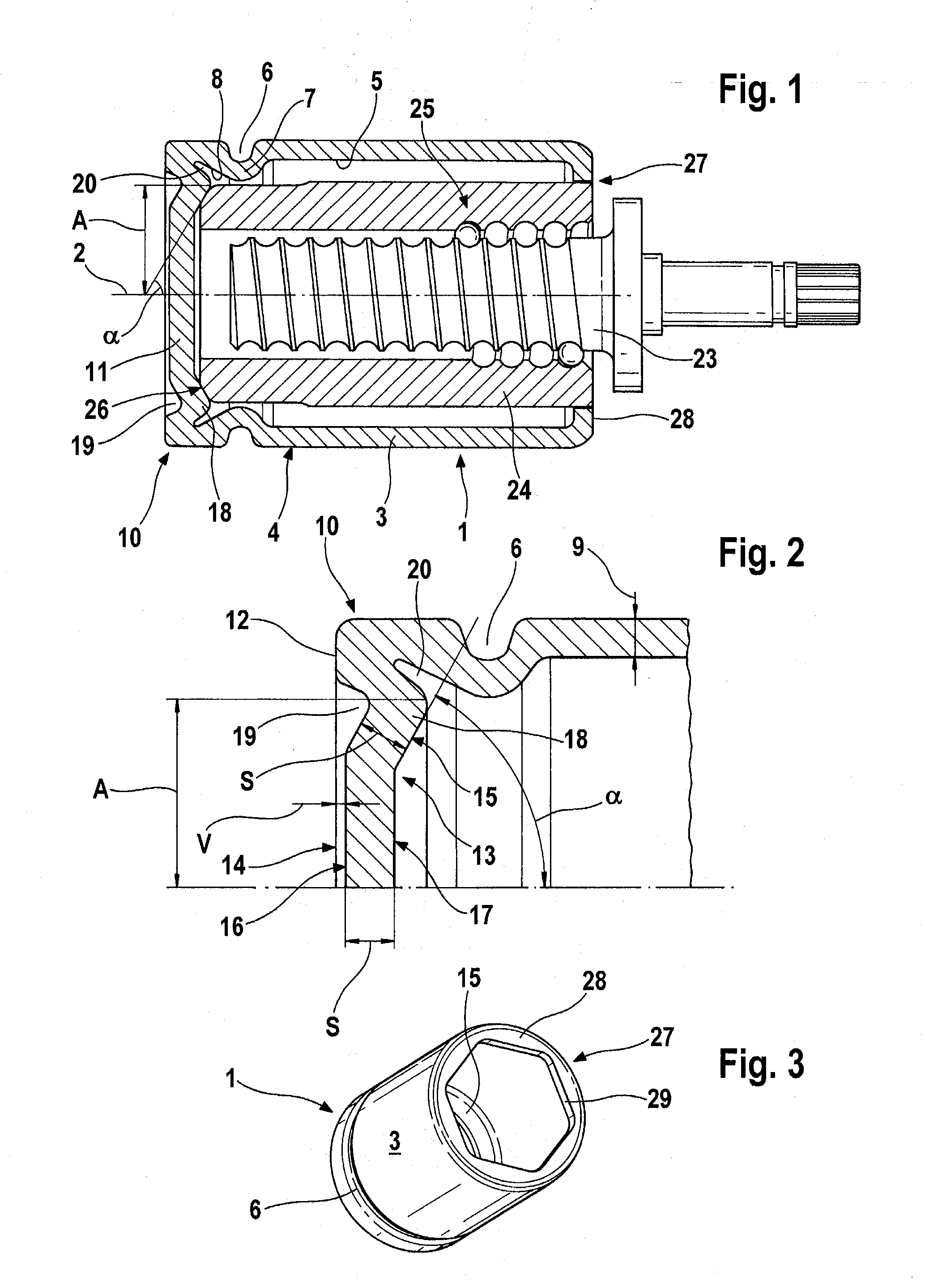
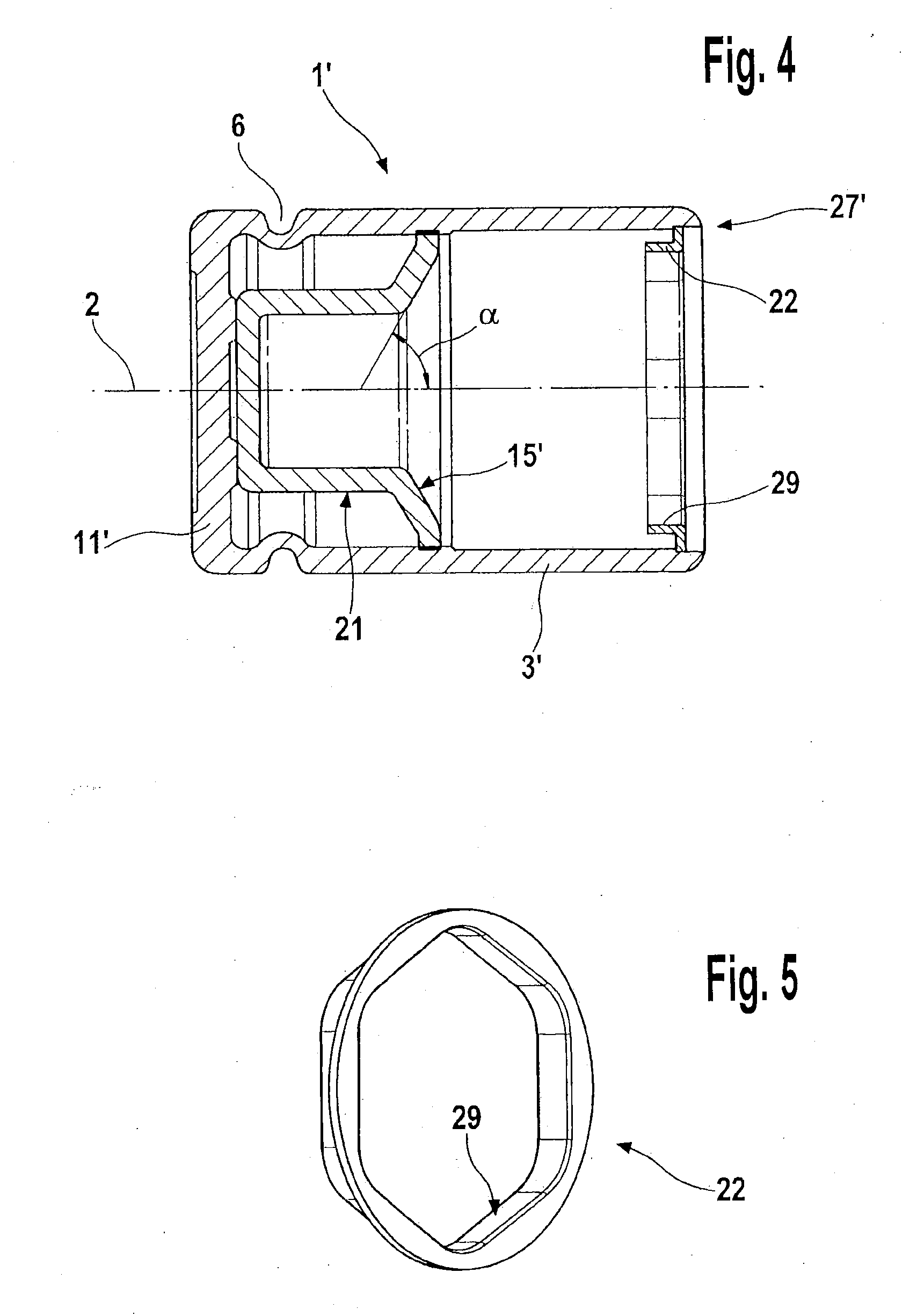
[0026]In the figures, parts of a disk brake for a motor vehicle are shown, in some cases schematically and enlarged.

[0027]FIG. 1 shows a piston 1 with a drive spindle 23 and a drive nut 24 in longitudinal section. The piston 1, which is embodied in such a way as to be rotationally symmetrical about a longitudinal axis 2, is configured as a pot which is open at one end, having a wall 3 and a piston head 11, it being possible for the piston head 11 to be placed against a brake pad (not shown) at the closed end of the piston 1 by means of an axial contact surface 12. The contact surface 12 is larger than a cross-sectional area 9 at the weakest point of the wall 3. Moreover, a circumferential groove 6 is rolled into an outer side 4 of the wall 3 in the vicinity of the contact surface 12, the said groove serving to receive a piston protection cap (not shown) when the piston is installed in the brake caliper. The contour of the rolled-in groove 6 is continued throughout the entire cross s...


PUM


Abstract

A multi-part piston for a brake saddle of a hydraulically and/or mechanically and/or electromechanically actuated disk brake is described herein. The piston is a pot open on one side and including a base and a wall attached thereto in one piece. The base can be impinged by brake pressure coming from the inside of the pot so that an outward-facing abutting surface of the base can be pressed against a brake lining. The inside of the pot receives at least one pressure piece associated with a parking brake mechanism. For simplified manufacture in the form of a modular piston system for use in various applications, it is proposed that the pressure piece and the base comprise conical surfaces facing one another for transferring braking pressure.

Description

CROSS REFERENCE TO RELATED APPLICATIONS[0001]This application is a continuation of PCT International Patent Application No. PCT / EP2009 / 057175, filed Jun. 10, 2009, which claims priority to German Patent Application No. 10 2008 028 412.2, filed Jun. 17, 2008, German Patent Application No. 10 2009 001 712.7, filed Mar. 20, 2009, and German Patent Application No. 10 2009 017 167.3, filed Apr. 9, 2009, the contents of such applications being incorporated by reference herein. This application is also a continuation-in-part of U.S. patent application Ser. No. 12 / 739,808, filed Apr. 26, 2010, which is a U.S. National Phase Patent Application of PCT / EP2008 / 064348, filed Oct. 23, 2008 that claims priority to German Patent Application No. 10 2007 051 456.7, filed Oct. 27, 2007, the contents of such applications being incorporated by reference herein.FIELD OF THE INVENTION[0002]The invention relates to a multi-part piston construction for a hydraulically and / or mechanically and / or electromecha...

Claims


Application Information

Patent Timeline
IPC IPC(8): F01B31/00
CPCF16D2125/06F16J1/12F16J1/006F16D2125/40F16D65/567F16D2121/14
Inventor WINKLER, THOMASZEIBIG, UWEKOCH, DIRKKLIMT, ANJABAUER, HERWIG
Owner CONTINENTAL TEVES AG & CO OHG
Why Eureka
Try Eureka