Head rest adjustment device

a positioning mechanism and head restraint technology, applied in the direction of chairs, pedestrian/occupant safety arrangements, vehicular safety arrangements, etc., can solve the problems of large play, large room occupation, and high cost of such positioning mechanisms

a positioning mechanism and head restraint technology, applied in the direction of chairs, pedestrian/occupant safety arrangements, vehicular safety arrangements, etc., can solve the problems of large play, large room occupation, and high cost of such positioning mechanisms

US6871913B2Inactive Publication Date: 2005-03-29LEAR CORP

Image

  • Head rest adjustment device
  • Head rest adjustment device
  • Head rest adjustment device

Examples


Embodiment Construction

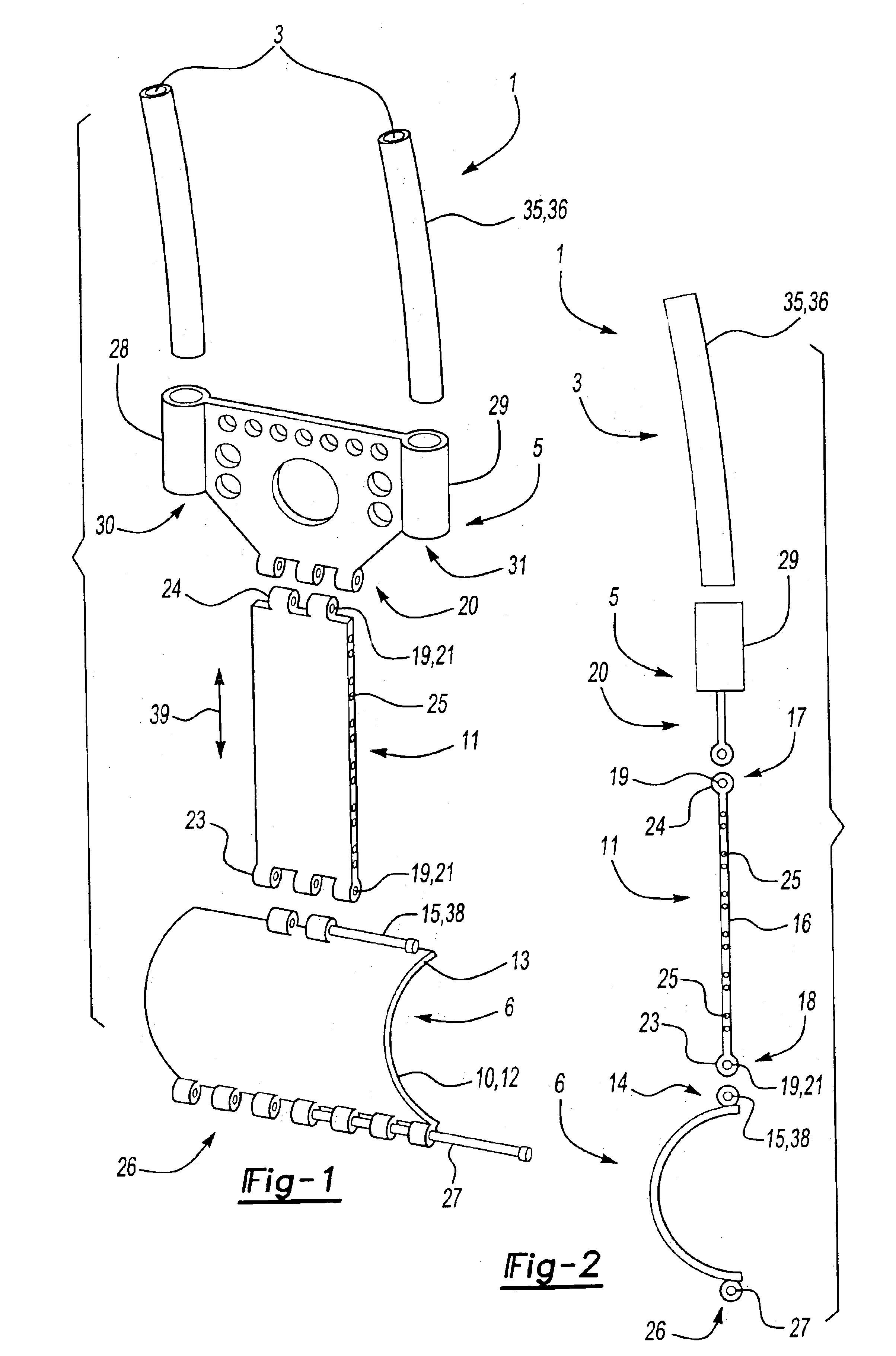
FIG. 1 shows a perspective front view of an embodiment of the head restraint positioning mechanism 1 according to the invention with different components in an exploded representation.

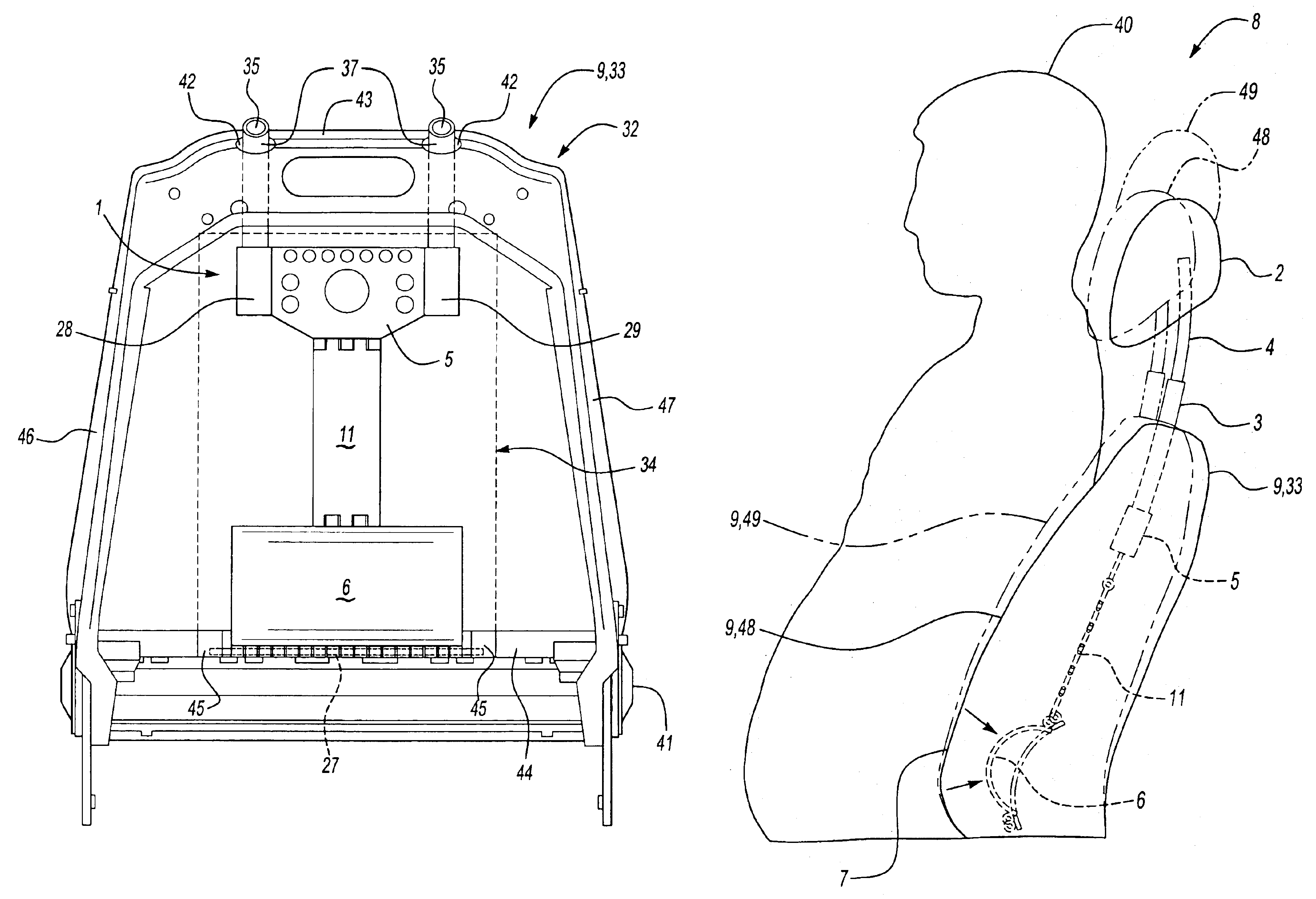
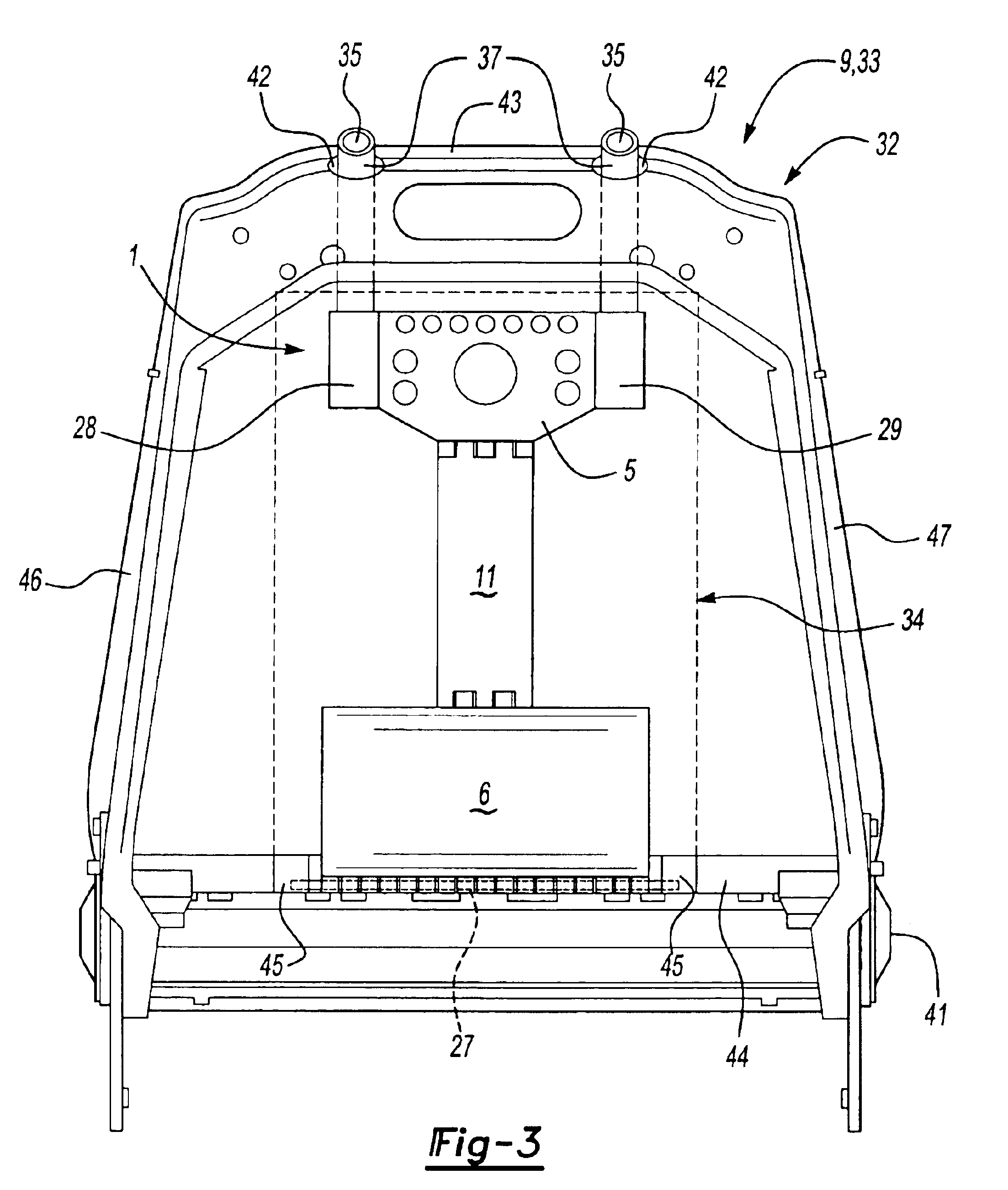
The head restraint positioning mechanism 1 includes two guide sleeves 3, a holding device 5, a connection element 11 and an impact device 6.

The guide sleeves 3 present a slight curvature and serve to retain the head restraint rods 4, see particularly FIG. 4. The head restraint rods 4 are adjustable within the guide sleeves 3, between different positions. In this way, adjustment for passengers of different sizes is facilitated so that the head restraint can always be arranged in the correct position relative to a passenger's head.

The lower ends of the guide sleeves 3 are inserted into sleeve retainers 28, 29 arranged on the side ends 30, 31 of the holding device 5. In the depicted embodiment, the guide sleeves 3 and sleeve retainers 28, 29 have anti-twisting cross-sections. The cross-section may be esse...


PUM


Abstract

A head restraint positioning device is provided for a head restraint of a vehicle seat. The head restraint positioning device includes an impact device movably connected to the head restraint and arranged on a seat back of the vehicle seat in the area of a pelvis of a passenger sitting on the vehicle seat. The impact device includes at least one structural unit that varies in length in response to the application of pressure and that causes a corresponding change in length of the impact device to change the position of the head restraint.

Description

BACKGROUND OF THE INVENTION1. Field of the InventionThe invention relates to a head restraint positioning mechanism for positioning a vehicle seat head restraint, particularly in the case of a rear-end impact to the vehicle. At least one impact device is arranged on a seat back of the vehicle seat and is movably connected to the head restraint. The impact device is, located in an area adjacent the pelvis of a passenger sitting on the vehicle seat.2. Background ArtA head restraint positioning mechanism is disclosed in DE 10206894. This mechanism serves to absorb the reaction forces acting on the passenger sitting in the vehicle seat during an impact, particularly a rear-end one, to the vehicle. The head restraint moves in the direction of the head of the passenger, whose head is securely supported by the restraint in case of impact. In this arrangement of the impact device, it must be noted that the center of gravity of the passenger is usually located approximately in the stomach / pe...

Claims


Application Information

Patent Timeline
29 Mar 2005
Publication
US6871913B2
IPC
A47C7/36; B60N2/42; B60N2/46; B60R21/055; B60N2/48; B60R21/00; B60N2/427; B60R22/28; B60R21/02; B60N2/75
CPC
B60N2/4885; B60N2/4808; B60N2/809; B60N2/888
Inventors
MALSCH, HEIKO; FISCHER, HARALD