
Impact dot print head and a printer including the same

a technology of impact dot and print head, which is applied in the direction of printing and other printing apparatus, can solve the problems of deteriorating magnetic flux flow efficiency between each armature and the yoke, reducing the attracting force of each armature to the associated core, and difficulty in maintaining a satisfactory state of contact between the armatures and the yoke. achieve the effect of high printing pressure and high printing speed

Inactive Publication Date: 2005-03-29
TOSHIBA TEC KK
View PDF10 Cites 24 Cited by
  • Summary
  • Abstract
  • Description
  • Claims
  • Application Information

AI Technical Summary

Benefits of technology

Accordingly, it is an object of the present invention to let a magnetic flux flow efficiently between an armature spacer and a yoke without complicating a manufacturing process.
It is a further object of the present invention to reduce the manufacturing cost.
It is a still further object of the present invention to attain a high printing speed and a high printing pressure.
In one aspect of the present invention there is provided a fitting structure for fitting an inner periphery-side cylindrical portion of a yoke and an inner periphery-side ring-shaped portion of an armature spacer to ensure a satisfactory state of contact between the inner periphery-side cylindrical portion of the yoke and the inner periphery-side ring-shaped portion of the armature spacer, thereby permitting a magnetic flux to flow efficiently between the armature spacer and the yoke through the contact portion between the inner periphery-side cylindrical portion of the yoke and the inner periphery-side ring-shaped portion of the armature spacer.
In another aspect of the present invention there is provided a fitting structure for fitting an inner periphery-side cylindrical portion of a yoke and an inner periphery-side ring-shaped portion of an armature spacer to ensure a satisfactory state of contact between the inner periphery-side cylindrical portion of the yoke and the inner periphery-side ring-shaped portion of the armature spacer, thereby permitting a magnetic flux to flow efficiently between the armature spacer and the yoke and hence permitting the attainment of a high printing speed and a high printing pressure.

Problems solved by technology

However, when there occur variations in the armature quality, it is difficult to maintain a satisfactory state of contact between the armatures and the yoke.
If the state of contact between the armatures and the yoke is unsatisfactory, the magnetic flux flowing efficiency between each armature and the yoke is deteriorated and the attracting force for attracting each armature to the associated core is decreased.
Recently various measures for attaining a high printing speed and a high printing pressure have been taken, but due to the aforesaid decrease of the attractive force which is caused by the generation of leakage flux it is difficult to attain a high printing speed and a high printing pressure to a satisfactory extent.
But the application of this grinding work results in an increase in the number of armature spacer manufacturing steps, and the manufacturing cost increases despite the adoption of the pressing work.
An attempt to decrease this variation results in a still higher manufacturing cost.

Method used


Image

  • Impact dot print head and a printer including the same
  • Impact dot print head and a printer including the same
  • Impact dot print head and a printer including the same

Examples


Embodiment Construction

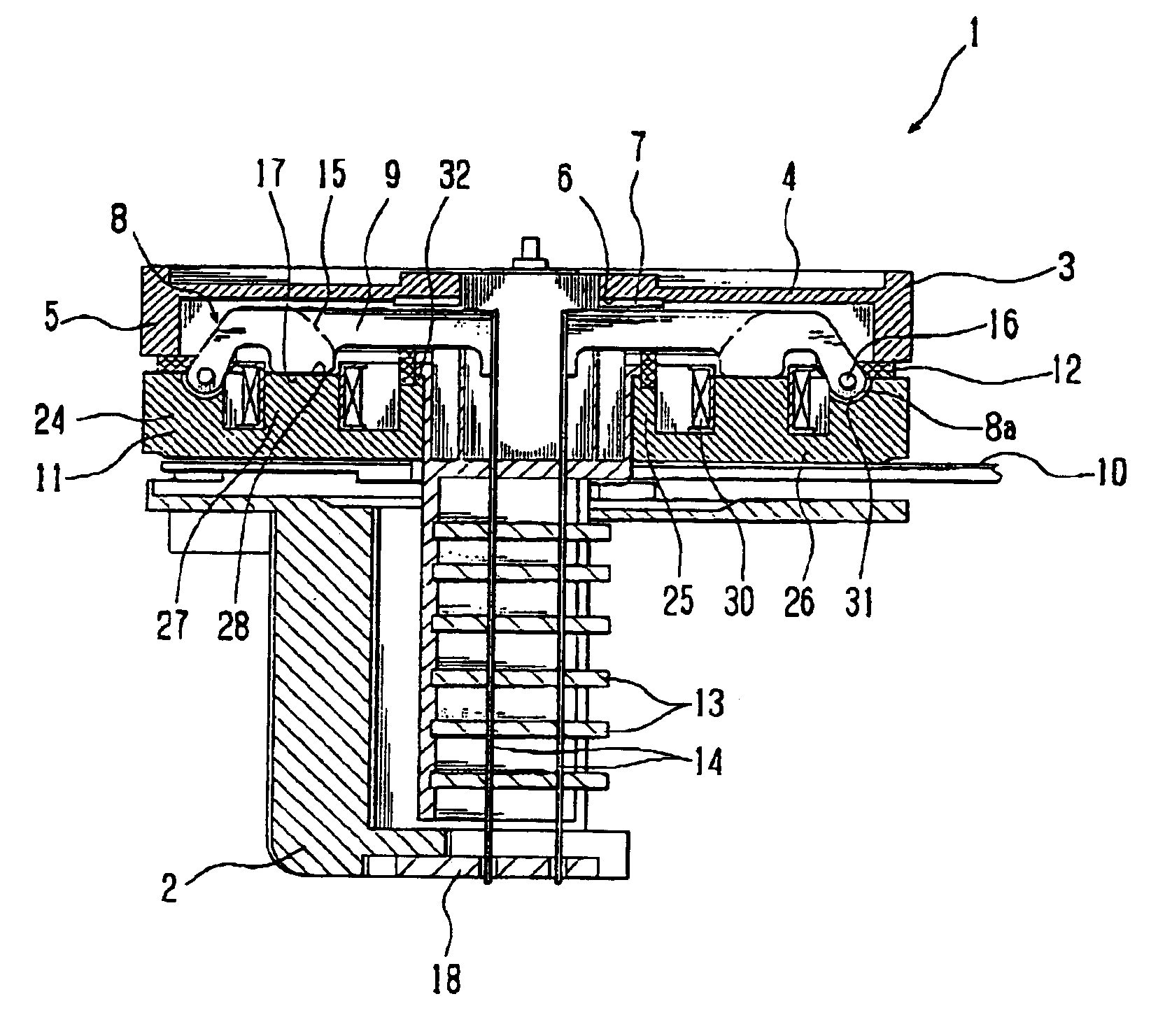
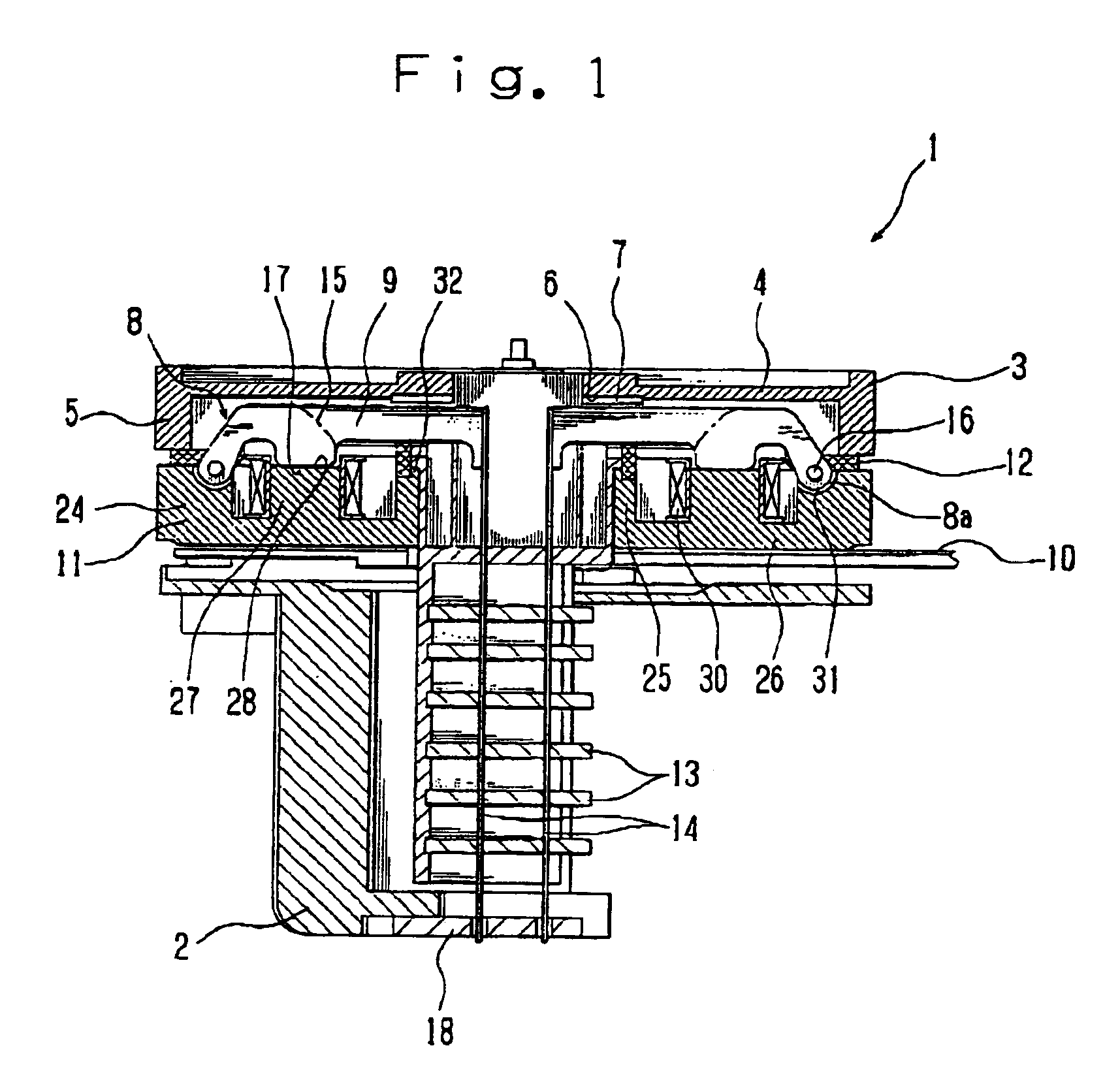
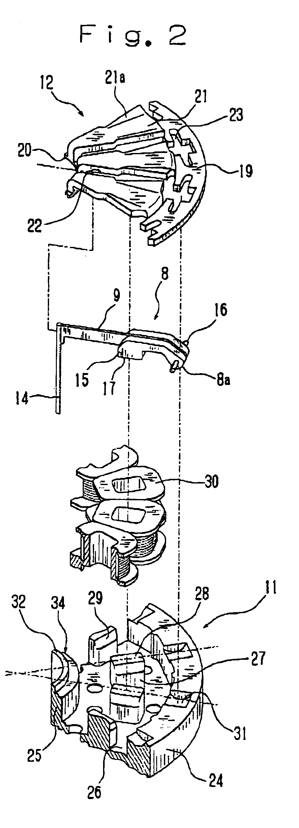
An embodiment of the present invention will be described below with reference to FIGS. 1 and 2.

First, a description will be given about an entire construction of an impact dot print head according to the present invention. FIG. 1 is a sectional side view showing an entire construction of an impact dot print head according to the present invention and FIG. 2 is an exploded perspective view showing a part thereof. The impact dot print head, indicated at 1, is provided with a front case 2 and a rear case 3 which are coupled together with mounting screws (not shown).

The rear case 3 has a cylindrical portion 5 which has a bottom 4 on one end side thereof. Centrally of the bottom 4 is formed a mounting recess 7 for mounting therein of a metallic, annular armature stopper 6.

The armature stopper 6 is mounted by being fitted in the mounting recess 7. When an armature 8 to be described later pivots from a printing position to a stand-by position, an arm 9 which is a part of the armature 8 com...


PUM


Abstract

In an impact dot print head there is provided a fitting structure for fitting an inner periphery-side cylindrical portion of a yoke and an inner periphery-side ring-shaped portion of an armature spacer with each other so that the inner periphery-side cylindrical portion of the yoke and the inner periphery-side ring-shaped portion of the armature spacer push against each other, thereby permitting a magnetic flux to flow efficiently between the armature spacer and the yoke through the contact face between the inner periphery-side cylindrical portion of the yoke and the inner periphery-side ring-shaped portion of the armature spacer.

Description

BACKGROUND OF THE INVENTION1. Field of the InventionThe present invention relates to an impact dot print head in a printer and more particularly to an impact dot print head wherein an armature is operated using a magnetic circuit to effect printing, the magnetic circuit being formed by allowing a magnetic flux which is generated by energizing a coil wound round a core provided in a yoke, to flow through an armature spacer, etc., as well as a printer using the impact dot print head.2. Description of Background ArtHeretofore there has been known an impact dot print head wherein an armature with a printing wire connected thereto is pivoted between a printing position and a standby position, and when the armature is pivoted to the printing position, a tip of the wire is brought into collision with recording paper to effect printing.In a certain impact dot print head of this type, a magnetic circuit is formed around the armature to be pivoted, the magnetic circuit causing the armature to...

Claims


Application Information

Patent Timeline
IPC IPC(8): B41J2/235B41J2/275
CPCB41J2/235
Inventor KAWAGUCHI, TAKAHIRO
Owner TOSHIBA TEC KK
Learn More