Dual action corn cob separation and improved chaffer for whole corn cobs

a corn cob and chaffer technology, applied in solid separation, agriculture tools and machines, agriculture, etc., can solve the problems of reducing the volume of cob residuals, reducing the volume of cobs to be dealt, and affecting the quality so as to prevent contamination, enhance the volume of whole corn cobs passing, and reduce the space

Inactive Publication Date: 2009-07-28
BLUE LEAF I P INC
View PDF29 Cites 51 Cited by
  • Summary
  • Abstract
  • Description
  • Claims
  • Application Information

AI Technical Summary

Benefits of technology

[0011]The combines of the invention are axial flow combines which use, for its threshing zone, one or more horizontally arranged rotors which are rotated in associated threshing cages or chambers, and which cages are partly constituted of threshing and separating concaves and partly of grates. The crop material is subjected to a much longer threshing and separation cycle than in conventional combines and therefore, the efficiency of axial flow machines is greater. A higher degree of separation is reached and the grain losses are reduced.
[0015]In accordance with this invention, the past chaffer sieves for corn cobs, on such combine harvesters, are replaced by improved sieves having elongated fingers on its louvered vanes, at the rear portion of the sieve. The improved rear portion constitutes from 75 to 60% of the surface of the sieve and each of the improved elongated fingers are greater than 3 inches in length. Previously, chaffer sieves for cleaning corn or cobs have such fingers being limited to no longer than 1.125 to 1.625 inches. In the present invention, whole cobs pass through the improved rear portion of the sieve, while the stalks, husks and other leafy material other than grain and cobs are kept out. The corn kernels are separately cleaned from the chaff at the front portion of the sieve. A substantial advantage of the improved rear portion fingers is provided by the finger's humped-back or rounded design, which serves to reorient the cobs flowing onto the sieve widthwise, to turn them lengthwise into the sieve openings, thus allowing whole cobs to fall through the sieve openings, while simultaneously serving as sufficient interference to stalks and husks passing over, so that fan-driven streams of air conventionally flowing from underneath the sieve can blow away whatever MOGC was not removed by the rotor. This sufficiently prevents contamination when cleaning the cobs. Furthermore, at the rear end of the sieve there is an adjustable dam portion that can be raised or lowered to stop the cobs from moving off the sieve.
[0016]In view of the above, and in accordance with the present invention, there is provided a combine cleaning system including a fan and a sieve which cooperate with each other to further separate the kernels of corn from the whole corn cobs (having had their kernels removed previously during threshing), and to further separate the whole cobs from the MOGC. The fan provides a substantially uniform flow of air up and through the sieve. The sieve comprises a slatted and louvered section or portion (with louvers being adjusted) extending rearwardly from a forward end of the sieve, and a louvered and elongated finger, corn cob cleaning portion downstream from the louvered grain cleaning area. The louvered grain cleaning portion, at the front of the sieve is configured to accommodate a flow of air therethrough from the fan and provides a level of cleaning to the threshed corn kernels blowing MOGC upwards and out of the rear end of the combine. The kernels of corn will fall through the louvered section having standard finger lengths of 1.125 to 1.625 inches and standard spacing between the fingers on the louvers of approximately 1⅝ inches. This forward corn kernel cleaning section comprises from 25 to 40% of the cleaning area of the sieve. The elongated finger section provides a second level of cleaning to the corn crop materials received thereon which are predominantly whole corn cobs and leafy material which may have passed through the rotor and are received from said rotor. This second level of cleaning to the materials received thereon allows whole corn cobs to pass through the spaces between elongated louvered fingers while receiving a flow of air blowing upward and rearwardly from the fan which serves to blow MOGC away from the chaffer sieve. This rearward, elongated finger, second portion constitutes 75 to 60%, preferably 66.7%, of the sieve's cleaning surface.
[0017]The front portion of the sieve is very standard and well known for collecting kernels of corn in the normal course of cleaning grain from the rotor of the combine harvester, but that portion is towards the front end and takes up less space of the sieve than does the rear portion. The rear elongated finger portion of the sieve is referred to as the corn cob collecting portion. Its spacing between elongated fingers is at least 3 inches wide. The rear portion is particularly characterized by the shape of said fingers, their length and the functional role played in reorienting the direction of whole corn cobs, so as to substantially enhance the volume of whole cobs passing therethrough.

Problems solved by technology

However, using stationary shellers limited the volume of cobs which had to be dealt with.
However, this caused pieces of cob to lodge in the fingers and plug the chaffer.
Thus, only reduced volumes of cob residuals could be obtained for corn-and-cob-mix products.
One drawback was the cobs could not be directly retrieved from the combine harvester.
His process and the special features of his combine design still limited harvesting to only cobs having lengths which did not exceed 2-3 inches.
He found that the cobs could not be effectively separated from the stalks, husks, etc. through the use of air.
However, the system although allowing for the 2 inches between fingered vanes of the chaffer to allow the width of the cobs, offers no other sieve design modifications.
If the cobs were broken up, they would require storage in a dry environment, and much greater cost.
Gordon pointed out that the proper opening between louvers is necessary, but if the opening is too large, straw and other material fall through contaminating the grain.

Method used


Image

  • Dual action corn cob separation and improved chaffer for whole corn cobs
  • Dual action corn cob separation and improved chaffer for whole corn cobs
  • Dual action corn cob separation and improved chaffer for whole corn cobs

Examples


Embodiment Construction

[0026]While the present invention is susceptible of embodiment in various forms, there is shown in the drawings a presently preferred embodiment thereinafter described, with the understanding that the present disclosure is to be considered as an exemplification of the invention and is not intended to limit the invention to the specific embodiment illustrated.

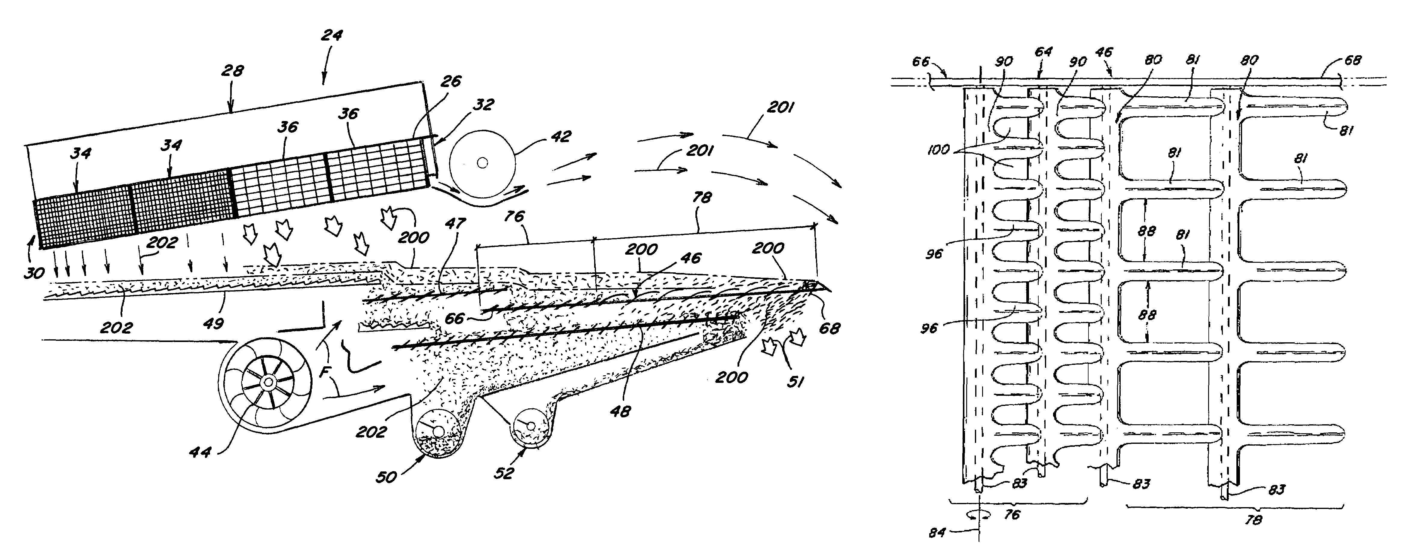
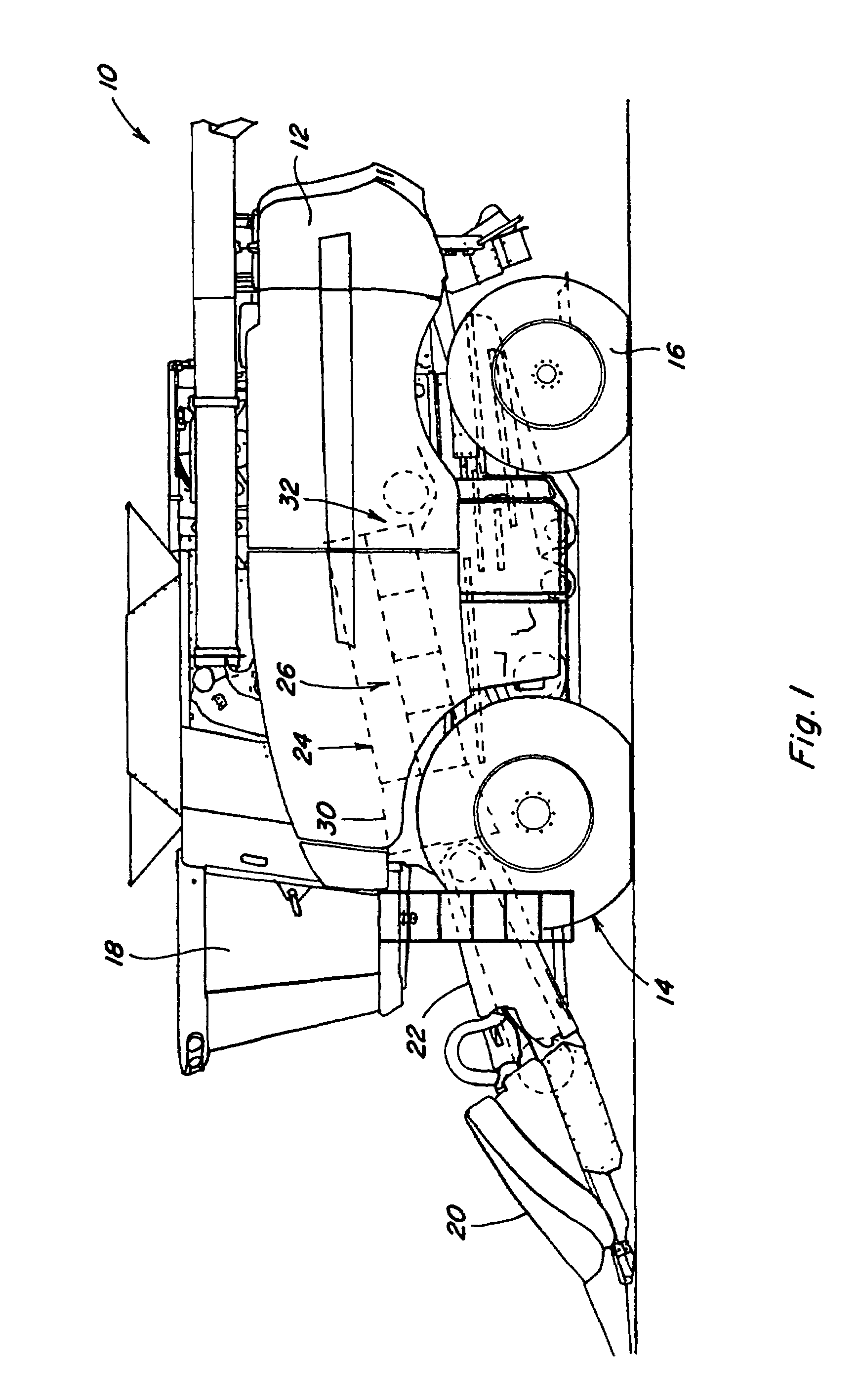
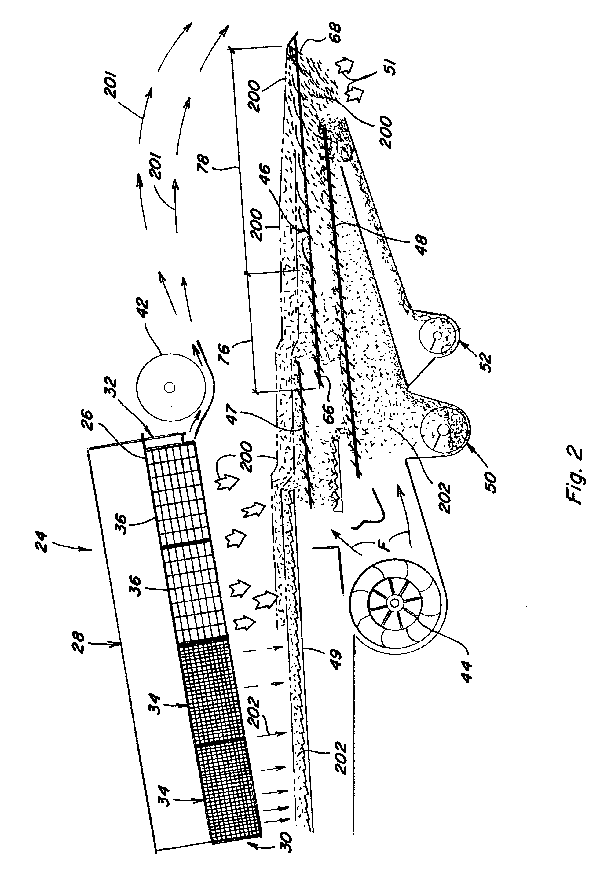
[0027]Referring now to the drawings, wherein like reference numerals refer to like parts throughout the several views, there is shown in FIG. 1 a self-propelled combine 10. The combine 10 includes a body, or housing, 12 supported on front drive wheels 14 and steerable rear wheels 16. The combine is powered by an engine (not shown) and controlled from an operator station 18. A crop harvesting apparatus or header 20 and a feeder mechanism 22 are attached at a forward end of the combine. The feeder mechanism 22 feeds harvested corn crop material to a threshing zone or section 24, of an axial flow rotary type combine which includes ...


PUM


Abstract

A dual action corn cob cleaning separation system having a whole corn cob sieve with elongated and rounded finger extensions for reorienting corn cobs traveling widthwise to instead travel lengthwise.

Description

TECHNICAL FIELD[0001]This invention relates to the threshing, separating, and cleaning of corn cobs, and particularly to the cleaning of whole corn cobs, to remove MOGC (material other than grain or cobs), after the corn kernels have been separated from the cobs. The MOGC is comprised of, for example, stalk portions, leaves, husks, tassels or silks, and other debris of generally lighter density than the cobs. This invention even more particularly relates to improvements for chaffer sieves employed on combine harvesters, to separate whole corn cobs from other residue.BACKGROUND ART[0002]Corn cobs have, for many years, added a certain measure of value to the harvest. Prior to the early 60's, the common corn harvesting practice was to pick the ears in the field, transport the crop to corn cribs, and later shell the corn off the cob at stationary shellers. The need to dispose of the cobs, after shelling, spurred most of the early research for useful corn cob end products. However, using...

Claims


Application Information

Patent Timeline
Patent Type & Authority Patents(United States)
IPC IPC(8): A01F12/32B07B1/00
CPCA01F12/32A01F11/06
Inventor RICKETTS, JONATHAN E.YODER, DENVER R.
Owner BLUE LEAF I P INC
Why Eureka
Try Eureka