Heat dissipation system

a heat dissipation system and heat dissipation tube technology, applied in indirect heat exchangers, lighting and heating apparatus, semiconductor/solid-state device details, etc., can solve the problems of increased manufacturing cost of heat pipes, and increased heat pipe pressure, so as to achieve efficient heat transfer, great heat dissipation area, and enhanced capillary

Inactive Publication Date: 2006-07-13
HON HAI PRECISION IND CO LTD
View PDF11 Cites 48 Cited by
  • Summary
  • Abstract
  • Description
  • Claims
  • Application Information

AI Technical Summary

Benefits of technology

[0012] The heat dissipation system has two passages to dissipate heat from a heat-generating component. One is the heat sink, while the other is the heat pipe. In the heat sink aspect, the fins provide a great heat dissipation area. The substrate can efficiently transfer heat to the fins as well as to the heat pipe.
[0013] In the heat pipe aspect, due to the hydrophilic layer formed on the wick of the heat pipe, the capillarity of the wick is enhanced. Thus, the working fluid is driven to flow from a condensation section of the heat pipe back to an evaporation section of the heat pipe more rapidly In addition, the protective layer on the exterior surface of the shell maintains the degree of vacuum within the heat pipe in a desired range and enhances heat flow from the substrate to the shell. Thus, the stability, working lifetime, and heat transfer capability of the heat pipe are improved by the presence of the shell. Furthermore, employing surface laser texturing treatment and vacuum coating technologies gives the heat pipe a more compact inner structure and promotes more efficient heat flow. Therefore, a thermal transfer efficiency of the heat dissipation system is improved.

Problems solved by technology

However, this solution commonly requires high rigidity materials for the heat pipe shell, which increase the cost of manufacturing the heat pipe.
Further, even slight damage to the heat pipe may result in leakage of air into the heat pipe and an increase in the pressure in the heat pipe (i.e., a decreased degree of vacuum).
If this happens, the heat pipe may fail to work altogether.
The heat pipe generally has a variety of other limitations, such as a capillary pumping rate limit, a nucleate boiling limit, and an entrainment limit, all of which constrain the ability of the heat pipe to cool the electronic and electrical components.
When the first of any of these limitations is reached, the heat pipe cannot provide any further improvement in its operating capacity.
Furthermore, a heat dissipation system in a form of a heat pipe has a limited dissipation area so that the heat conductive efficiency thereof is limited.

Method used


Image

  • Heat dissipation system
  • Heat dissipation system
  • Heat dissipation system

Examples


Embodiment Construction

[0020] Embodiments of the present heat dissipation system now be described in detail below with reference to the drawings.

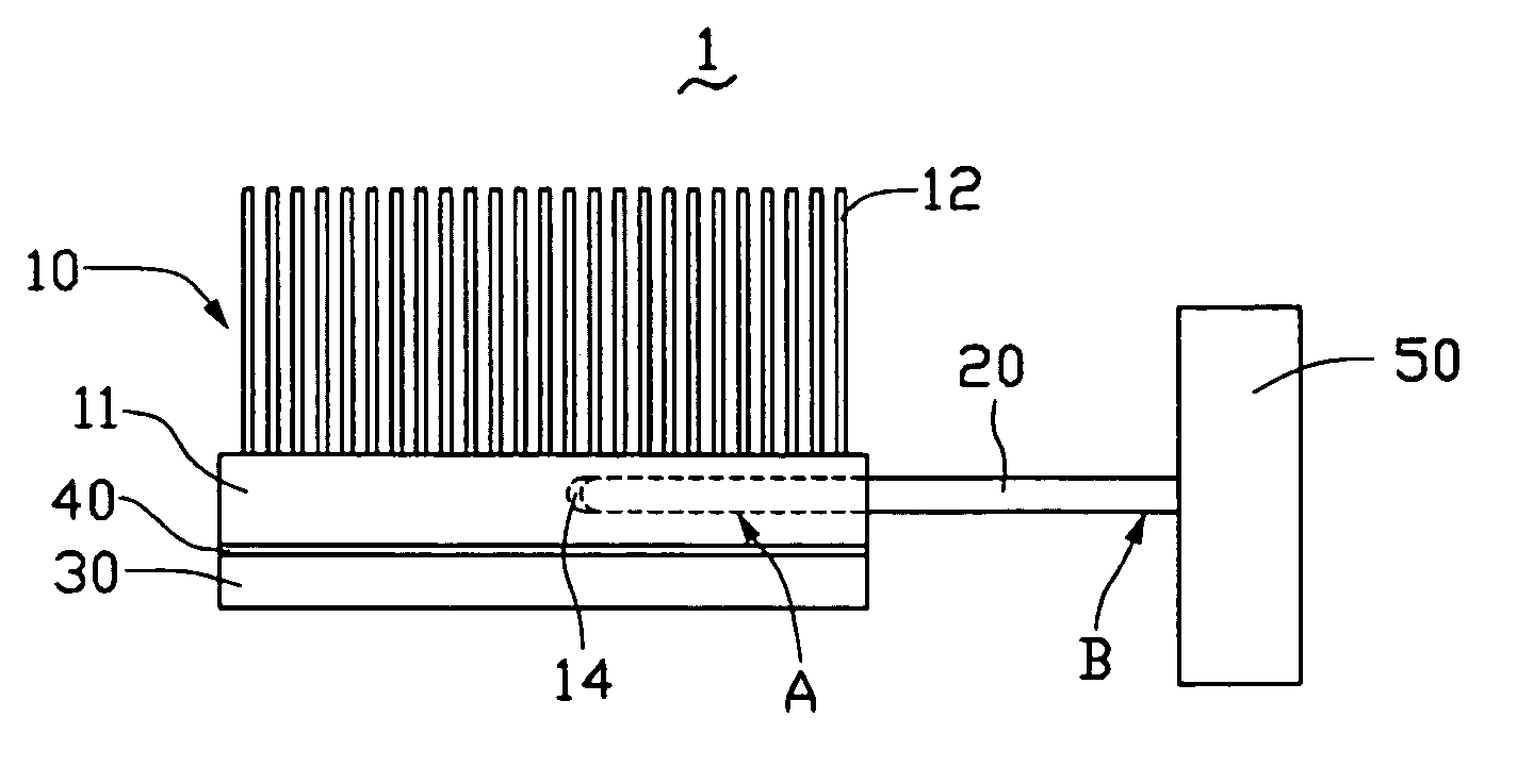
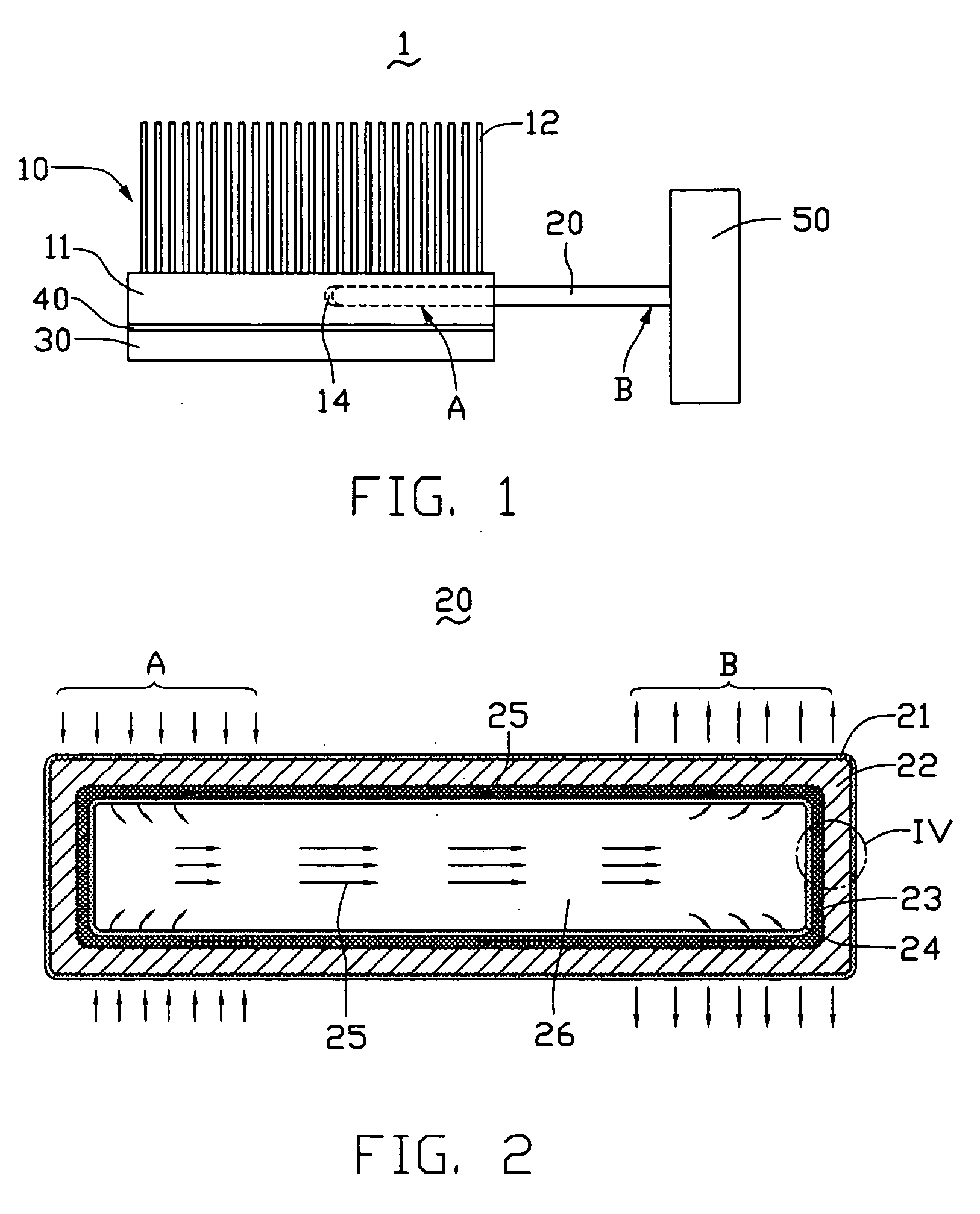
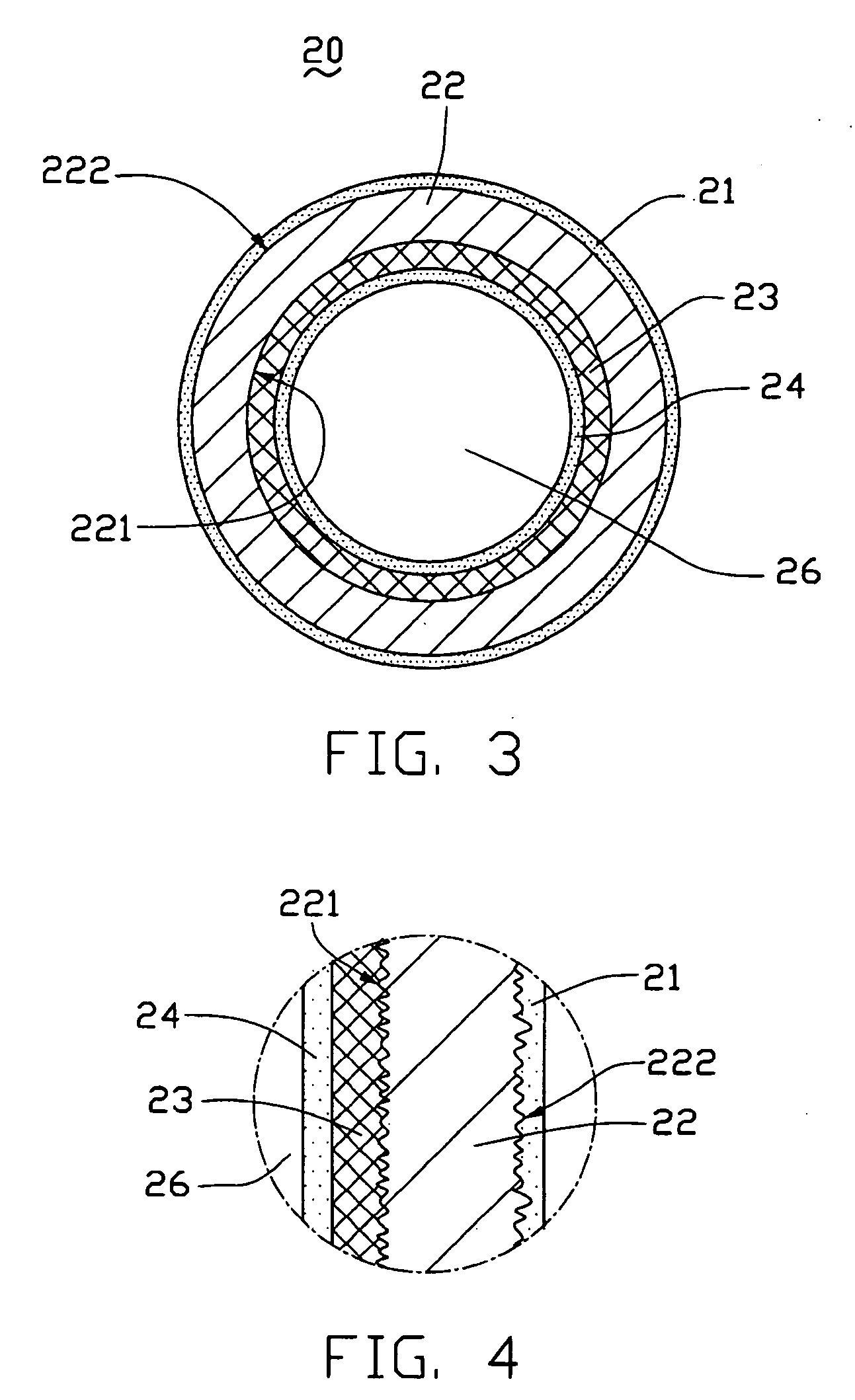
[0021]FIG. 1 illustrates a heat dissipation system 1 in accordance with a preferred embodiment. The heat dissipation system 1 includes a heat sink 10, a heat pipe 20, and a cooling assembly 50. The heat sink 10 includes a substrate 11 and a number of fins 12 extending from a surface thereof. The heat pipe 20 generally has two opposite end sections, i.e., an evaporation section “A” and a condensation section “B”. The substrate 11 has a receiving portion 14 for the insertion of the evaporation section “A” of the heat pipe 20 thereinto. The cooling assembly 50 is disposed adjacent the condensation section “B” of the heat pipe 20 and is configured for promoting heat transfer away from the heat pipe 20.

[0022] The substrate 11 and the fins 12 are advantageously made of a metal displaying excellent thermal conductivity and good oxidation resistance, preferably a mater...


PUM

PropertyMeasurementUnit
thicknessaaaaaaaaaa
thicknessaaaaaaaaaa
thicknessaaaaaaaaaa

Abstract

A heat dissipation system includes a heat sink, a heat pipe, and a cooling assembly. The heat sink includes a substrate and a number of fins extending therefrom. The heat sink has a receiving portion. The heat pipe includes a shell, a wick, and a working fluid contained in the shell. The heat pipe has an evaporation section and a condensation section. The evaporation section is inserted into the receiving portion of the substrate while the condensation section is equipped with the cooling assembly. A hydrophilic layer is formed on the wick so that the capillarity of the wick is enhanced. The heat dissipation system has two mechanisms by which to dissipate heat from a heat-generating component, i.e., via the heat sink and the heat pipe. Therefore, an efficiency of heat dissipation of the heat dissipation system is improved.

Description

CROSS-REFERENCE TO RELATED APPLICATION [0001] This application is related to a copending U.S. patent application Ser. No. 11 / 141,094 filed on May 31, 2005, and entitled “HEAT PIPE WITH HYDROPHILIC LAYER AND / OR PROTECTIVE LAYER AND METHOD FOR MAKING SAME”, with the same assignee. The disclosure of the above-identified application is incorporated herein by reference.TECHNICAL FIELD [0002] The present invention relates to heat dissipating devices and, more particularly, to a heat dissipation system having a heat pipe, which can efficiently dissipate heat from a heat-generating component. DISCUSSION OF THE RELATED ART [0003] At present, electronic and electrical components, such as central processing units (CPUs) and engines of vehicles, exist a general tendency towards faster operational speeds and greater functional capabilities. When a CPU or an engine operates at high speeds or a high capacity in a limited enclosure, its temperature may increase greatly. Thus, it is desirable to qui...

Claims


Application Information

Patent Timeline
Patent Type & Authority Applications(United States)
IPC IPC(8): H05K7/20F28D15/02
CPCF28D15/02F28D15/046F28D2021/0029H01L23/427F28F19/02H01L2924/0002F28F2245/02H01L2924/00
Inventor CHEN, GA-LANE
Owner HON HAI PRECISION IND CO LTD
Why Eureka
Try Eureka