Slip form paver

a technology of slip form and slop, which is applied in the direction of roads, roads, highways, etc., can solve the problems of insufficient rigidity of the track assembly, inconvenient work interruption, and severe problems, and achieve the effect of increasing the rigidity of the structur

Inactive Publication Date: 2005-03-29
WIRTGEN GMBH
View PDF9 Cites 69 Cited by
  • Summary
  • Abstract
  • Description
  • Claims
  • Application Information

AI Technical Summary

Benefits of technology

The invention advantageously provides that the longitudinal guide for the working means has a predetermined length and is supported at the machine frame for free displacement transverse to the working direction without adaptation to a certain working height. The longitudinal guide is unitary so that the working means may be reciprocated as desired on the longitudinal guide without any transition. Moreover, the longitudinal guide it

Problems solved by technology

Such interruption of the work is undesirable so that slip-form pavers have been developed which have machine frames that can the widened telescopically (WO95/28525, WO97/04176).
While it is relatively simple to change the frame width of the machine frame telescopically, severe problems may arise if at the same time also the working means have to be telescopically changed in the working width.
It is

Method used


Image

  • Slip form paver
  • Slip form paver
  • Slip form paver

Examples


Embodiment Construction

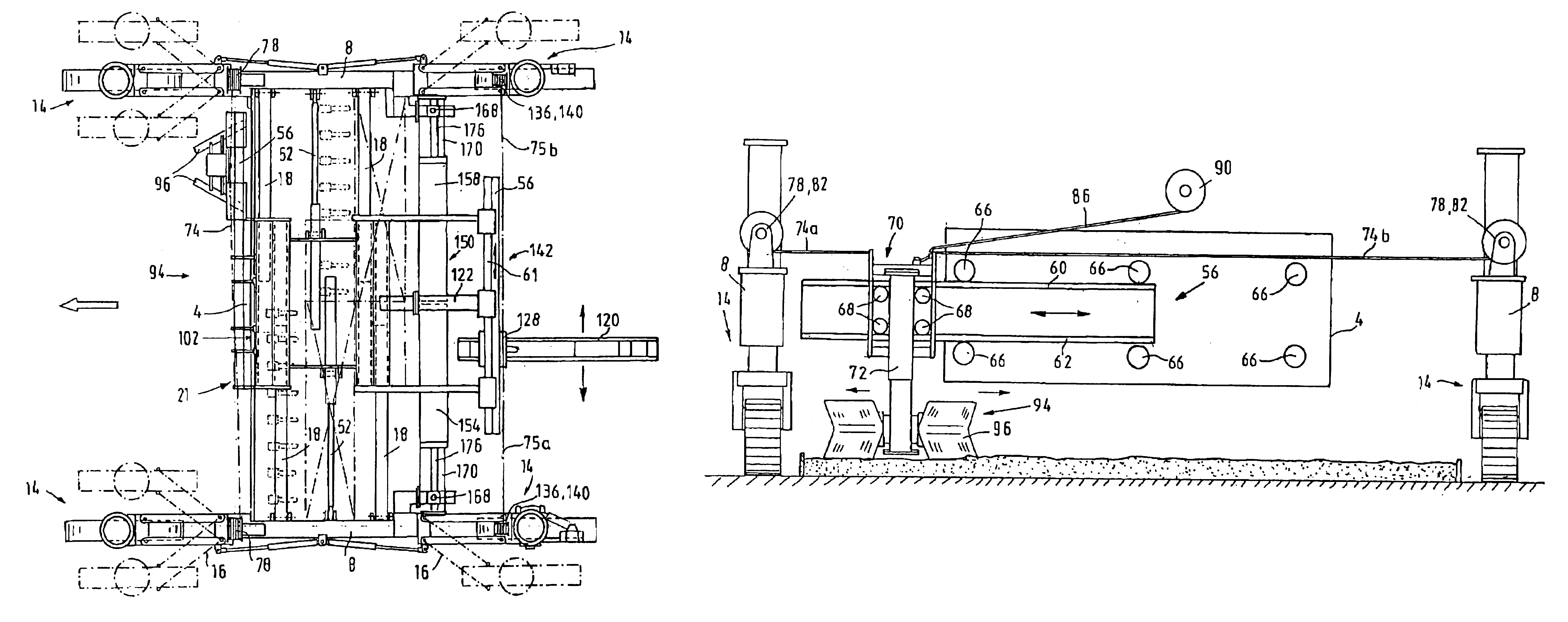
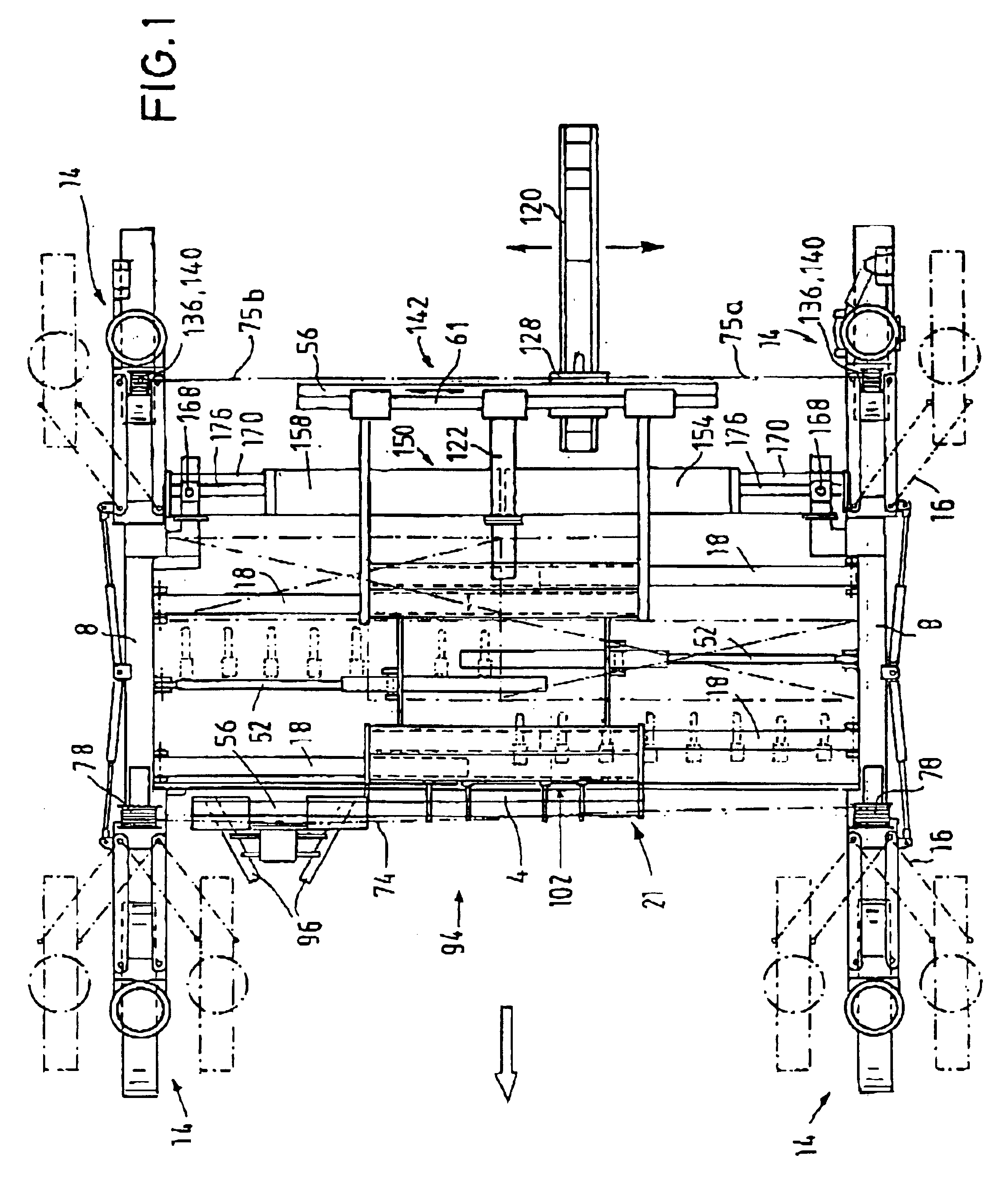
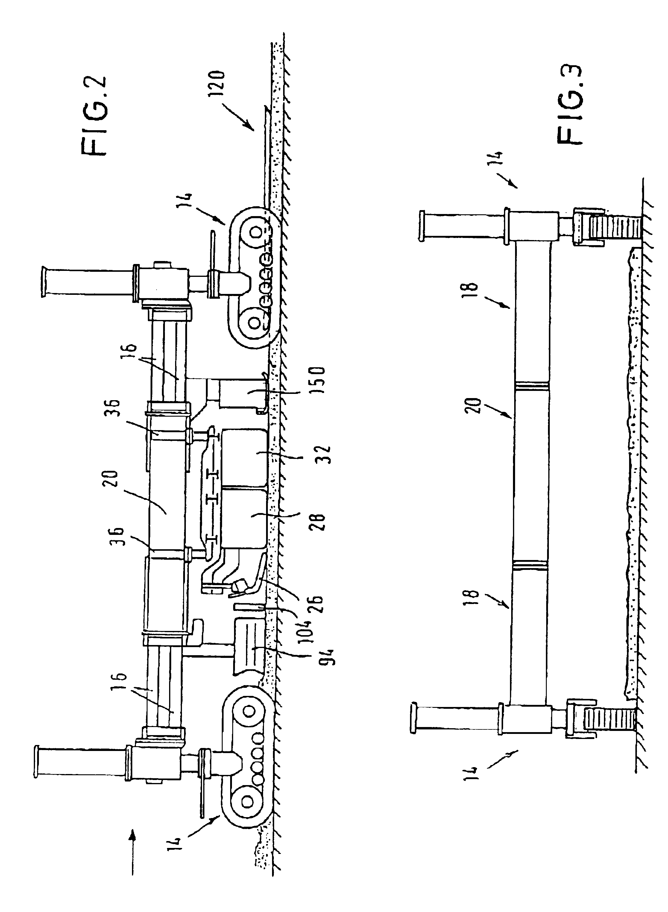
The slip-form paver has a tractor 2 consisting of a machine frame 4 with longitudinal beams 8 extending in parallel to the working direction and telescopically movable cross beams 18 extending transverse to the working direction for variably adjusting the working width. The cross beams are supported in a base frame 20, a total of four cross beams 18 projecting from a base frame arranged in the middle of the working width and being connected with the longitudinal beams 8.

The cross beams 18 are mutually offset in the base frame 20 so that, for example, the working width may be varied between 3 m and 6 m. The cross beams 18 may also be adapted for double telescopic extension should substantially larger working widths be desired to be set.

At the front and the rear end of the longitudinal beams 8, a respective track assembly 14 is articulately fastened guided in a parallelogram-like manner. The parallelogram guide that allows for a track width adjustment without changing the working widt...


PUM


Abstract

In a slip-form paver comprising a tractor (2) consisting of a machine frame (4) telescopable at least transversely to the traveling direction, with working means being mounted thereto, where at least one of the working means is displaceable along a longitudinal guide (56) across the entire working width transversely to the traveling direction, characterized in that the longitudinal guide (56) for the working means as a predetermined length and is supported at the machine frame (4) for free displacement transversely to the working direction without adjustment to a certain working width.

Description

BACKGROUND OF THE INVENTIONSuch slip-form pavers are required for making concrete road surfaces. Known slip-form pavers comprise a tractor consisting of a machine frame and four track assemblies carrying different working means for spreading and smoothing the concrete.Since the desired width of the concrete lanes can vary, for example at merging lanes, a rearrangement of the slip-form paver is often required which can take a restructuring time of two to three days depending on the necessary extent of the restructuring work.Such interruption of the work is undesirable so that slip-form pavers have been developed which have machine frames that can the widened telescopically (WO95 / 28525, WO97 / 04176).While it is relatively simple to change the frame width of the machine frame telescopically, severe problems may arise if at the same time also the working means have to be telescopically changed in the working width.From DE-A-198 14 052, it is known to mount the machine frame with a transv...

Claims


Application Information

Patent Timeline
IPC IPC(8): E01C19/22E01C19/40
CPCE01C19/40E01C2301/18
Inventor AESCHLIMANN, WERNERSMOLDERS, RAYMOND
Owner WIRTGEN GMBH
Why Eureka
Try Eureka