Manufacturing method of compound aspheric lens

a technology of compound aspheric lens and manufacturing method, which is applied in the field of manufacturing compound aspheric lens, can solve the problems of low efficiency percentage, achieve the effects of reducing deactivation and deterioration, enhancing efficiency percentage, and reducing the number of lenses

Inactive Publication Date: 2005-03-29
FUJI PHOTO OPTICAL CO LTD
View PDF7 Cites 5 Cited by
  • Summary
  • Abstract
  • Description
  • Claims
  • Application Information

AI Technical Summary

Benefits of technology

Even though bubbles (air bubbles) are prevented from entering the molded resin layer, at the step of separating the cured molded resin layer obtained by ultraviolet irradiation of the resin fluid, sandwiched between the lens and the metallic mold, from its interface with the metallic mold, exfoliation arises on the interface between the molded resin layer and the lens or white feather-like cracks or fissures occur in the molded resin layer of the manufactured compound aspheric lens, resulting in a low efficiency percentage.
In view of these problems, the present invention is intended to enhance the efficiency percentage by making it difficult for bubbles (air bubbles) to enter the molded resin layer at the manufacturing step by a different method from the prior patented invention and preventing cracks, fissures, exfoliation or the like from occurring in the molded resin layer of the manufactured compound aspheric lenses.
The present invention can serve to enhance the efficiency percentage because bubbles are prevented from entering the resin fluid by bringing the ultraviolet-curable resin fluid and the lens into point contact with other, or bringing the resin fluid dropped onto the concave lens into point contact with the aspheric face of the metallic mold and bringing the lens close to the metallic mold in this state. In particular, the present invention makes it not only possible but also easier than the patented invention described above to manufacture lenses even having a large aspheric face or a large central thickness of the molded resin layer. Furthermore, supplying nitrogen gas into the syringe storing ultraviolet-curable resin fluid and purging the fluid with this nitrogen gas can serve to restrain deactivation and deterioration of the ultraviolet-curable resin stored in the syringe and thereby to ensure the curing of the resin fluid by irradiation with ultraviolet rays, resulting in prevention of fissures, cracks, exfoliation and other faults in the molded resin layer and accordingly in an enhanced efficiency percentage.

Problems solved by technology

Even though bubbles (air bubbles) are prevented from entering the molded resin layer, at the step of separating the cured molded resin layer obtained by ultraviolet irradiation of the resin fluid, sandwiched between the lens and the metallic mold, from its interface with the metallic mold, exfoliation arises on the interface between the molded resin layer and the lens or white feather-like cracks or fissures occur in the molded resin layer of the manufactured compound aspheric lens, resulting in a low efficiency percentage.

Method used


Image

  • Manufacturing method of compound aspheric lens
  • Manufacturing method of compound aspheric lens
  • Manufacturing method of compound aspheric lens

Examples


embodiment 1

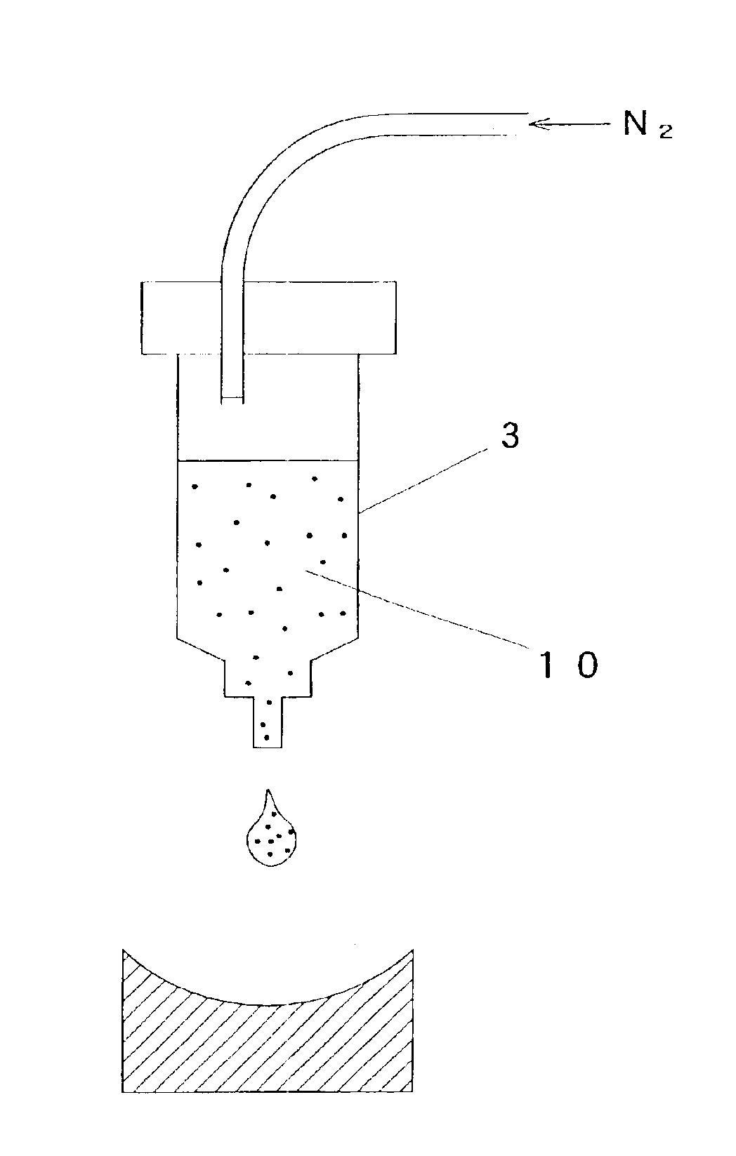
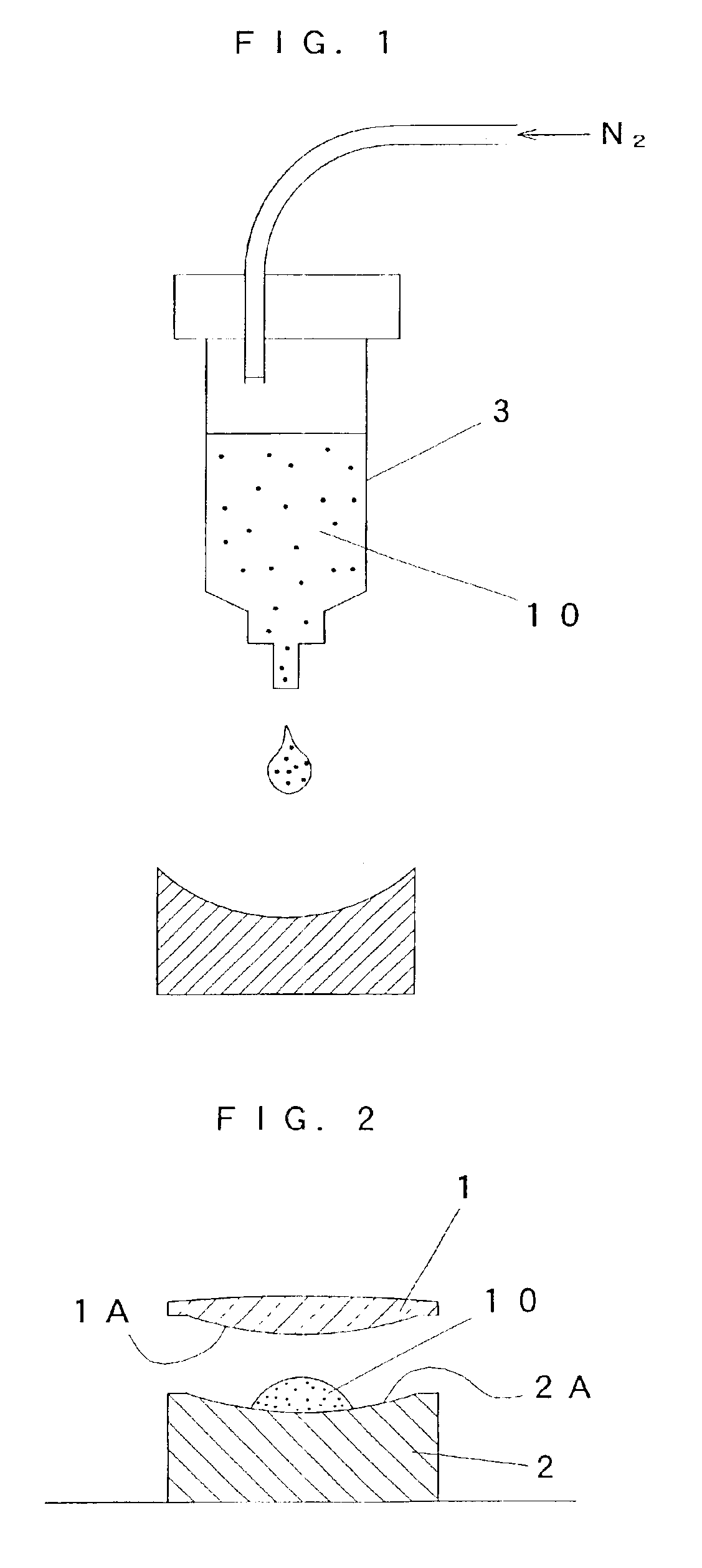
In Embodiment 1 and Comparative Example 1, a composite aspheric face was produced by using as the convex lens to constitute the base of the aspheric lens a glass lens of 200 μm in central thickness, φ57 mm in outside diameter and R99 in radius of curvature (see FIG. 2), while in Embodiment 2 and Comparative Example 2, a composite aspheric face was produced by using as the concave lens to constitute the base of the aspheric lens a glass lens of 150 μm in central thickness, φ51 mm in outside diameter and R37 in radius of curvature (see FIG. 5). In any of the embodiments and the comparative examples, the compound aspheric lens was produced without allowing bubbles (air bubbles) to enter the molded resin layer 10A.

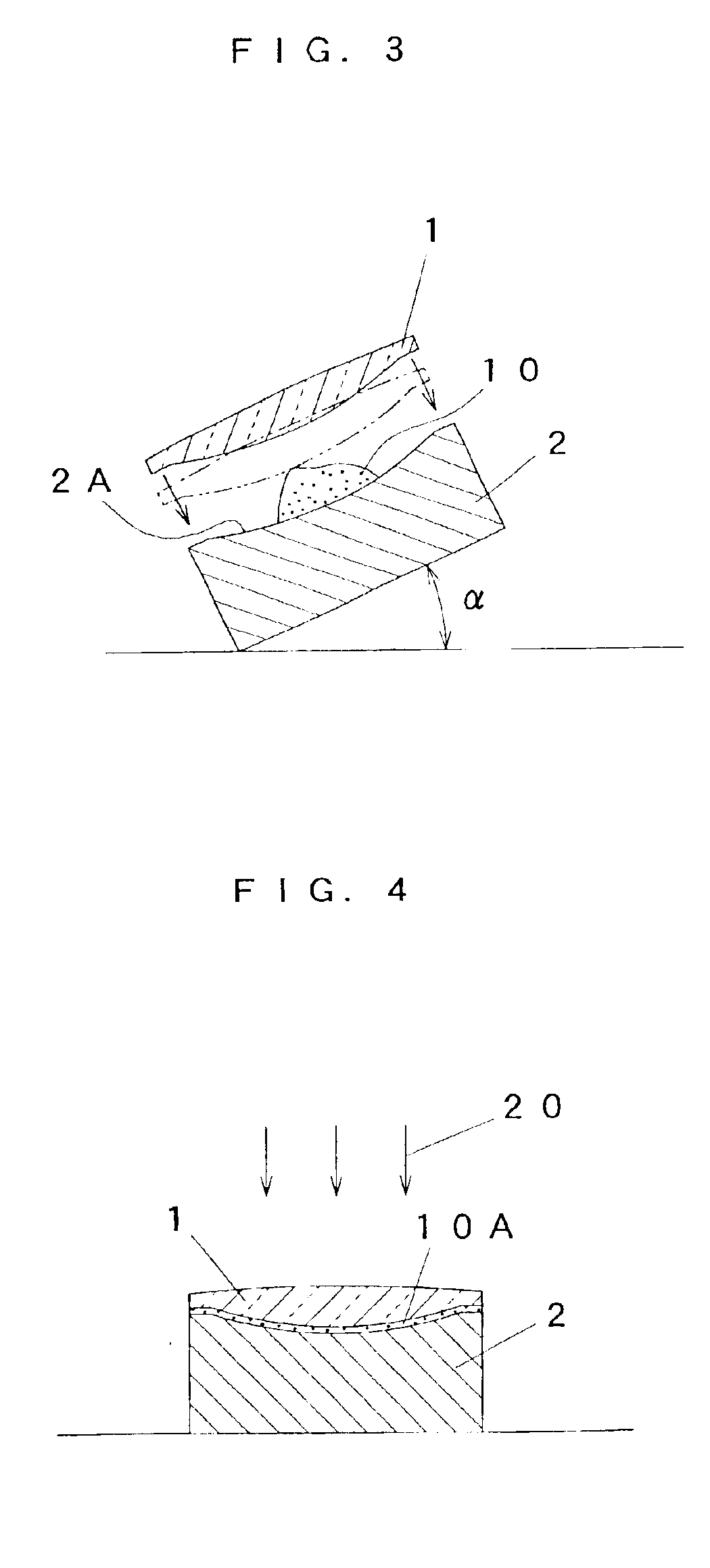
Thus in producing a compound aspheric lens having the convex lens 1 as its base (Embodiment 1 and Comparative Example 1), as in the embodiment of the invention shown in FIG. 2 through FIG. 4, the resin fluid 10 let stay on the aspheric face 2A of the concave metallic mold 2 an...


PUM

PropertyMeasurementUnit
angle of inclinationaaaaaaaaaa
thicknessaaaaaaaaaa
thicknessaaaaaaaaaa

Abstract

A method including: dropping the ultraviolet-curable resin fluid onto the aspheric face of a metallic mold set horizontally, the aspheric face having a desired concave face; bringing a convex lens close to the metallic mold and stopping the movement of the lens just before it comes into contact with the ultraviolet-curable resin fluid; inclining the metallic mold and the lens together to cause the ultraviolet-curable resin fluid to flux; after bringing the convex face of the lens into point contact with this fluxed and swelled ultraviolet-curable resin fluid, moving the lens to a prescribed position relative to the metallic mold to place the ultraviolet-curable resin fluid between the lens and the metallic mold; returning the lens and the metallic mold together from the inclined state to the horizontal state, thereby irradiating the ultraviolet-curable resin fluid with ultraviolet rays to cure the resin fluid and form a molded resin layer.

Description

BACKGROUND OF THE INVENTION1. Field of the InventionThe present invention relates to a method of manufacturing compound aspheric lenses.2. Description of the Related ArtLenses used in optical apparatuses including cameras and microscopes are mostly made of glass lens. Glass lenses are manufactured, each to have a desired curvature, by machining glass blocks (also known as lens blanks) produced by press-forming molten glass. Methods of manufacturing resin lenses are also in practice, by which resin instead of glass is press-formed, injection-molded, teemed or fabricated otherwise. These methods have the advantage of a lower manufacturing cost because, once molds are produced, they can be used for a large number of lenses. However, resin lenses have the fatal disadvantage of the high susceptibility of their optical performance to temperature variations, and therefore they are not used for precision lenses.Incidentally, there are lenses known as aspheric lenses, namely lenses whose sur...

Claims


Application Information

Patent Timeline
Patent Type & Authority Patents(United States)
IPC IPC(8): B29C39/42B29C39/24B29C39/10B29D11/00B29C35/08G02B3/00B29C39/02B29L11/00G02B3/02
CPCB29C39/10B29C39/24B29C39/42B29D11/00019B29D11/00413Y10S425/808B29C2791/005B29C2035/0827
Inventor KARITA, NOBUKI
Owner FUJI PHOTO OPTICAL CO LTD
Why Eureka
Try Eureka