Method for generating detail directed visibility elements for a graphics model

a graphics model and visibility element technology, applied in the field of computer graphics, can solve the problems of insufficient polygon production, prohibitively slow for large models, and poor quality models, and achieve the effect of more accurate decisions about visibility

Inactive Publication Date: 2005-03-29
MITSUBISHI ELECTRIC RES LAB INC
View PDF11 Cites 38 Cited by
  • Summary
  • Abstract
  • Description
  • Claims
  • Application Information

AI Technical Summary

Benefits of technology

It is an object of the present invention to generate detail directed visibility elements to enable more accurate decisions about the visibility of rendering elements such polygons and points.

Problems solved by technology

However, these techniques can still produce more polygons than needed.
Furthermore, their processing time is dependent on the number of polygons in the original model, which can be prohibitively slow for large models.
Finally, these methods can produce poor quality models when the polygon count is small.

Method used


Image

  • Method for generating detail directed visibility elements for a graphics model
  • Method for generating detail directed visibility elements for a graphics model
  • Method for generating detail directed visibility elements for a graphics model

Examples


Embodiment Construction

Introduction

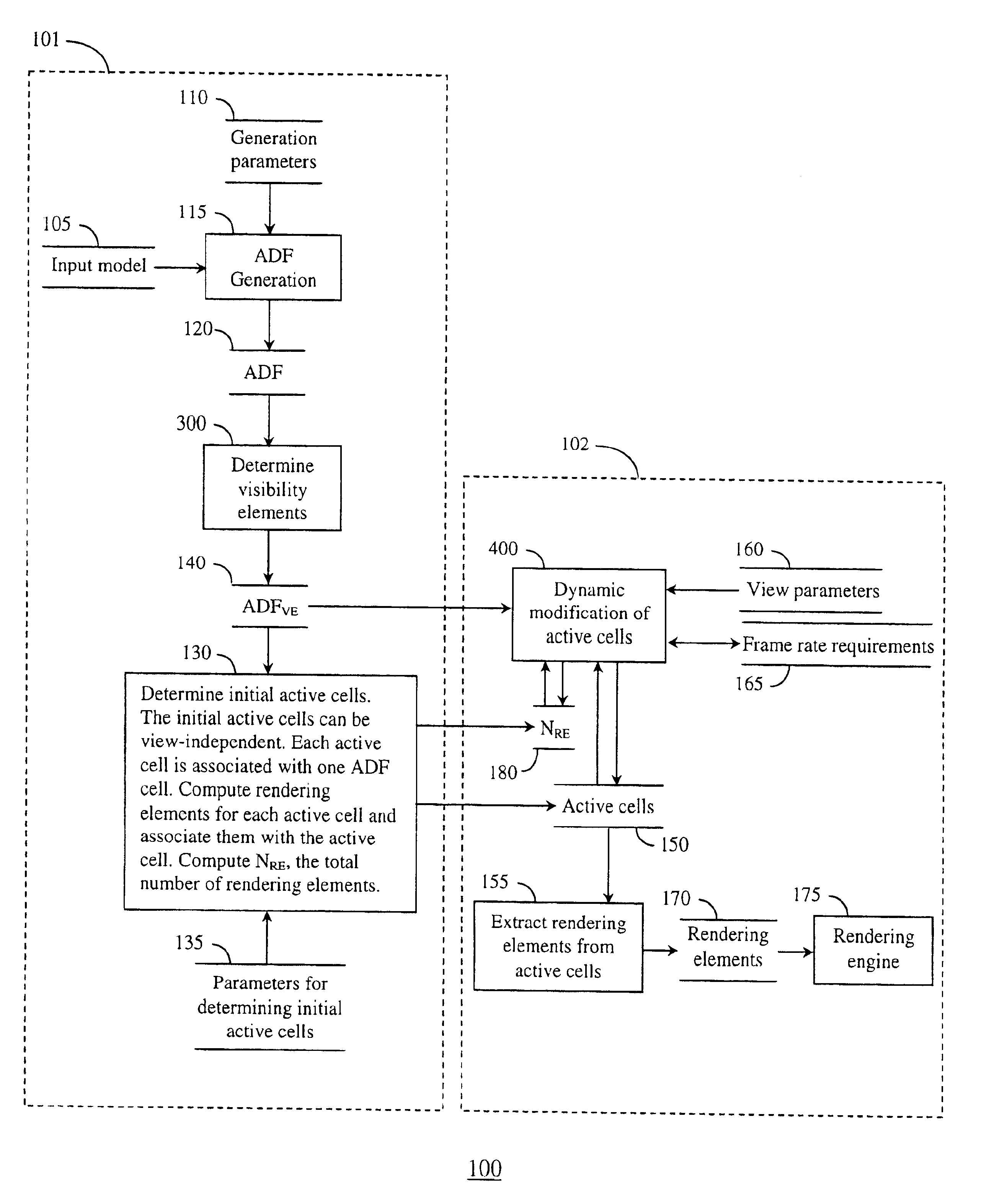
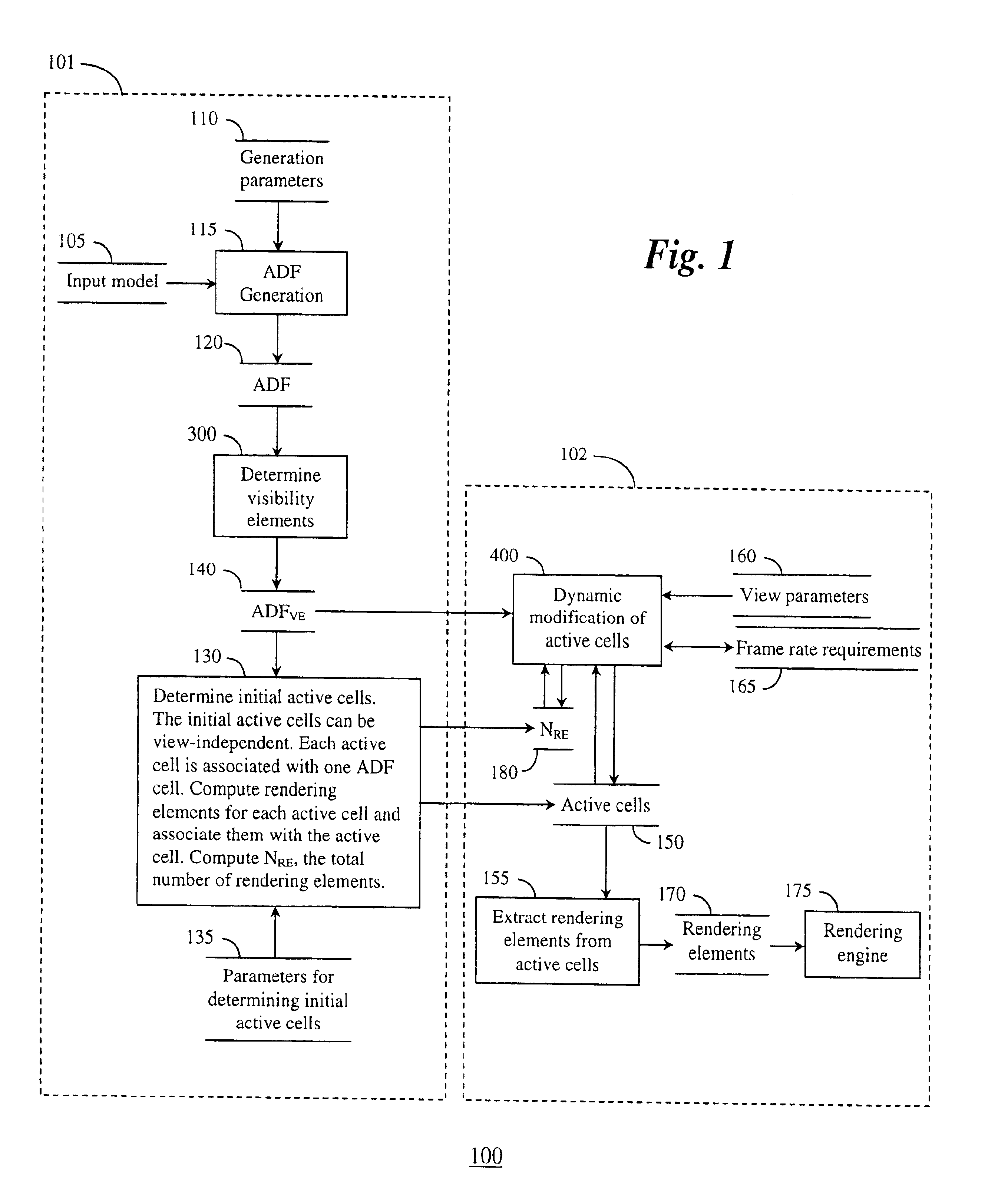
FIG. 1 shows a computerized dynamic modeling system and method 100 according to our invention. The modeling system and method 100, as a basis, uses an adaptively sampled distance field (ADF) 120 to represent a digitized model that can be animated, in real-time, for use by the entertainment industry and physical simulations.

The basic data structure of an ADF is described in U.S. patent application Ser. No. 09 / 370,091 “Detail-Directed Distance Fields” filed by Frisken et al. on Aug. 6, 1999, incorporated herein in its entirety by reference.

The ADF 120 can be generated from an input model 105 by a ADF generation method 115 according to generation parameters 110. For example, the generation parameters can specify a level-of-detail, or acceptable error measures. The method 115 adaptively samples distance values in a signed distance field of the model 105, and stores the distance values in a spatial hierarchy of cells, for example a sparse octree of cells. Distance values with...


PUM


Abstract

A method generates a detail directed hierarchical representation of orientations of a surface of a graphics model. The surface of the graphics model is partitioned into surface cells, each surface cell enclosing a portion of the surface. The surface cells are stored in a hierarchical data structure having levels, wherein the number of levels for a particular portion of the surface is determined by surface detail of the particular portion. A visibility element of the enclosed portion of the surface is determined for each surface cell, the visibility element specifying an axis and a spread defining a range of normal values of the enclosed portion of the surface. The visibility element is stored with the associated surface cell. The surface detail of the particular portion can be determined by a degree of curvature and shading parameters of the surface of the particular portion.

Description

FIELD OF THE INVENTIONThe present invention relates generally to the field of computer graphics, and more particularly to determining the orientations of a surface of a model.BACKGROUND OF THE INVENTIONIn real-time graphics applications, such as games and physical simulations, numerous techniques are known to automatically generate models in the form of polygon meshes. Common generation techniques include laser range scanning and triangulation of implicit functions. Often, the resultant meshes include more polygons that can be rendered by standard rendering engines at real-time frame rates.Therefore, in order to reduce the number of polygons in the models, multi-resolution triangle meshes are frequently used. These methods typically use two approaches for generating level-of-detail (LOD) meshes. In the static approach, a set of static LOD meshes are pre-computed before use in an application. At run-time, a member of the set is selected, based on viewing parameters and frame rate req...

Claims


Application Information

Patent Timeline
Patent Type & Authority Patents(United States)
IPC IPC(8): G06T15/40G06T15/10
CPCG06T15/40
Inventor PERRY, RONALD N.FRISKEN, SARAH F.POPE, JACKSON W. J.
Owner MITSUBISHI ELECTRIC RES LAB INC
Why Eureka
Try Eureka