System and method for improving piezoelectric micro-actuator operation by preventing undesired micro-actuator motion hindrance and by preventing micro-actuator misalignment and damage during manufacture

Inactive Publication Date: 2005-03-29
SAE MAGNETICS (HK) LTD
View PDF6 Cites 7 Cited by
  • Summary
  • Abstract
  • Description
  • Claims
  • Application Information

AI Technical Summary

Problems solved by technology

Further, the present means of attaching the FSA 204 to the arm 212 causes problems relating to assuring suspension stiffness and correct head attitude as well as other problems.

Method used


Image

  • System and method for improving piezoelectric micro-actuator operation by preventing undesired micro-actuator motion hindrance and by preventing micro-actuator misalignment and damage during manufacture
  • System and method for improving piezoelectric micro-actuator operation by preventing undesired micro-actuator motion hindrance and by preventing micro-actuator misalignment and damage during manufacture
  • System and method for improving piezoelectric micro-actuator operation by preventing undesired micro-actuator motion hindrance and by preventing micro-actuator misalignment and damage during manufacture

Examples


Embodiment Construction

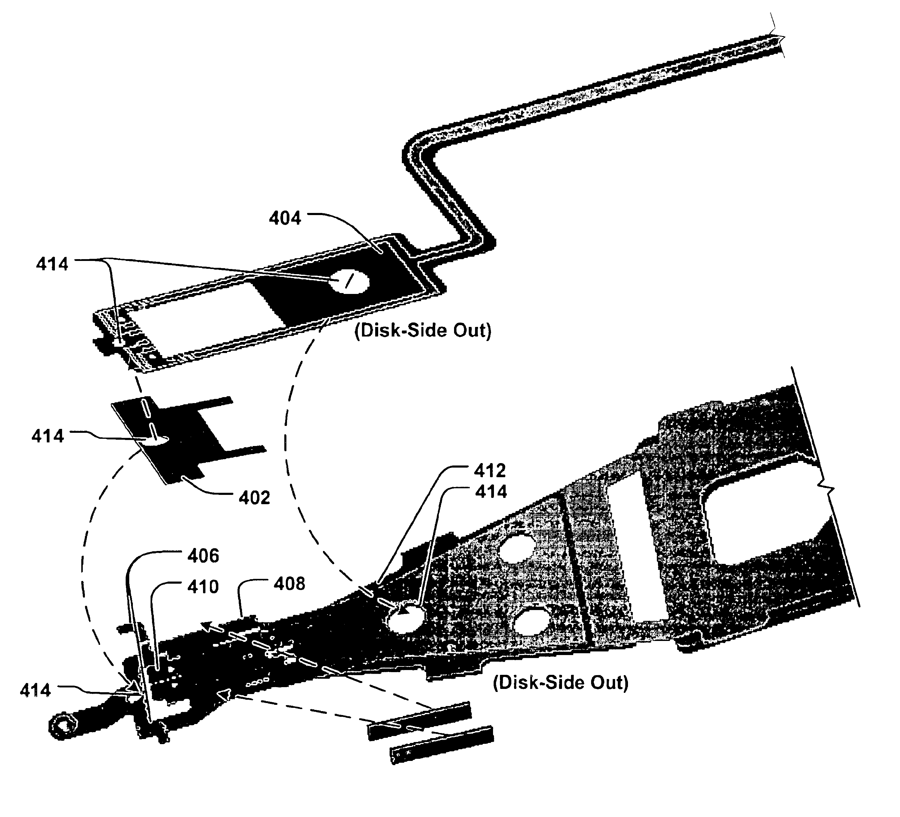
FIG. 3 provides illustrations of a drive arm with FSA under principles of the present invention. In one embodiment, the FSA has an (‘O’-shaped) opening that allows the FSA to fit over the micro-actuator 304 without interference. In an embodiment, the micro-actuator 304 is composed of an actuator frame 306 that cradles the head 308 and piezoelectric members 310 on either side to perform fine adjustments of the head 308 location. To provide shock resistance, a suspension tongue 312, which is attached to the actuator frame 306 by an adhesive such as epoxy or resin, is utilized. In another embodiment, the suspension tongue 312 is attached to the actuator frame 306 by a welded bond, such as by laser welding. The suspension tongue 312 is restrained at one end by a ‘hammer’ or ‘T’-shaped element (second hook element) 314 and supported at the other end by a dimple 316.

To provide correct suspension function and for proper head alignment in an embodiment, there needs to be a 25 to 50 micro-me...


PUM

PropertyMeasurementUnit
electricaaaaaaaaaa
recording densityaaaaaaaaaa
drive densityaaaaaaaaaa

Abstract

A system and method for improving piezoelectric micro-actuator operation by preventing undesired micro-actuator motion hindrance and by preventing micro-actuator misalignment during manufacture. A shim element is interposed between an electric circuit assembly and a lower portion of an actuator frame. The electric circuit assembly has a generally ‘O’-shaped portion configured so that an upper portion of said actuator frame is able to protrude through the ‘O’-shaped portion. The shim element is coupled between the electric circuit assembly and the lower portion of the actuator frame.

Description

BACKGROUND INFORMATIONThe present invention relates to magnetic hard disk drives. More specifically, the present invention relates to a system and method for improving piezoelectric micro-actuator operation by preventing undesired micro-actuator motion hindrance and by preventing micro-actuator misalignment.In the art today, different methods are utilized to improve recording density of hard disk drives. FIG. 1 provides illustrations of a typical drive arm configured to read from and write to a magnetic hard disk. Typically, voice-coil motors (VCM) 102 are used for controlling a hard drive's arm 104 motion across a magnetic hard disk 106. Because of the inherent tolerance (dynamic play) that exists in the placement of a recording head 108 by a VCM 102 alone, micro-actuators 110 are now being utilized to ‘fine-tune’ head 108 placement, as is described in U.S. Pat. No. 6,198,606. A VCM 102 is utilized for course adjustment and the micro-actuator 110 then corrects the placement on a mu...

Claims


Application Information

Patent Timeline
Patent Type & Authority Patents(United States)
IPC IPC(8): G11B5/48G11B5/55
CPCG11B5/5552G11B5/486
Inventor YAO, MINGGAOXIE, YIRU
Owner SAE MAGNETICS (HK) LTD
Why Eureka
Try Eureka