Vehicle tracking system

Active Publication Date: 2005-03-29
NISSAN MOTOR CO LTD
View PDF13 Cites 58 Cited by
  • Summary
  • Abstract
  • Description
  • Claims
  • Application Information

AI Technical Summary

Benefits of technology

Accordingly, one object of the present invention is to provide a preceding ve

Problems solved by technology

In short, it is difficult to reli

Method used


Image

  • Vehicle tracking system
  • Vehicle tracking system
  • Vehicle tracking system

Examples


second embodiment

Referring now to FIG. 8, a preceding vehicle tracking system in accordance with a second embodiment of the present invention will now be explained. In view of the similarity between the first and second embodiments, the parts of the second embodiment that are identical to the parts of the first embodiment will be given the same reference numerals as the parts of the first embodiment. Moreover, the descriptions of the parts of the second embodiment that are identical to the parts of the first embodiment may be omitted for the sake of brevity.

Basically, the preceding vehicle tracking system of the second embodiment of the present invention is identical to the first embodiment, except for the processing used for determining an enlargement / reduction ratio of the extracted portion of the input images 27 during the template matching process executed in the vehicle tracking processing section 105. In particular, in the second embodiment of the present invention, the edges of the preceding ...

third embodiment

Referring now to FIGS. 9-11, a preceding vehicle tracking system in accordance with a third embodiment of the present invention will now be explained. In view of the similarity between the first and third embodiments, the parts of the third embodiment that are identical to the parts of the first embodiment will be given the same reference numerals as the parts of the first embodiment. Moreover, the descriptions of the parts of the third embodiment that are identical to the parts of the first embodiment may be omitted for the sake of brevity.

The preceding vehicle tracking system in accordance with the third embodiment of the present invention differs from the first embodiment in that the preceding vehicle tracking system of the third embodiment is provided with a distance measuring sensor or device that is configured to measure a distance between a vehicle 1′ equipped with the preceding vehicle tracking system and the preceding vehicle 10 using a laser or other distance measuring dev...

fourth embodiment

Referring now to FIGS. 12 and 13, a preceding vehicle tracking system in accordance with a fourth embodiment of the present invention will now be explained. In view of the similarity between the first, second, third and fourth embodiments, the parts of the fourth embodiment that are identical to the parts of the first, second and third embodiments will be given the same reference numerals as the parts of the first, second and third embodiments. Moreover, the descriptions of the parts of the fourth embodiment that are identical to the parts of the second and third embodiment may be omitted for the sake of brevity.

Basically, the preceding vehicle tracking system in accordance with the fourth embodiment differs from the first embodiment in that two cameras 2a and 2b in stereoscopic are used instead of using a single camera and a distance image obtained based on the stereoscopic cameras 2a and 2b is used to track a preceding vehicle.

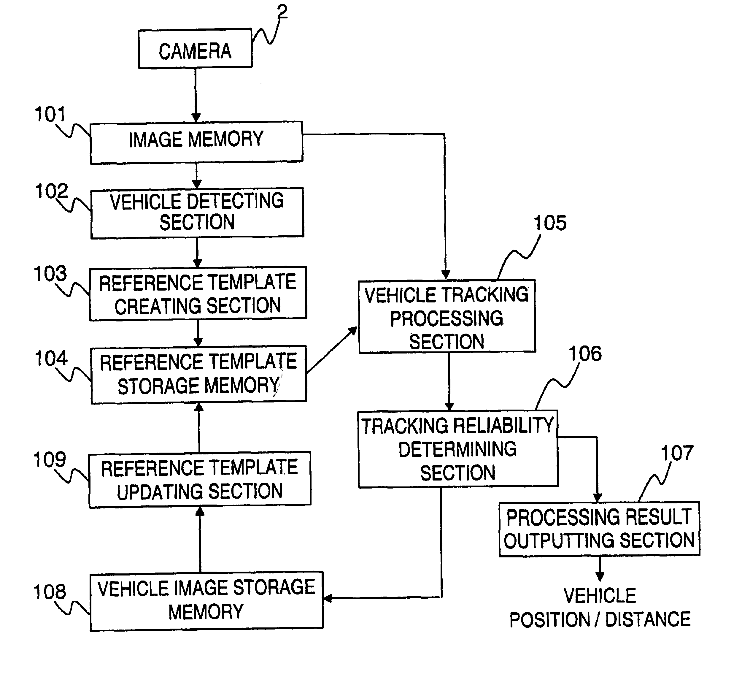
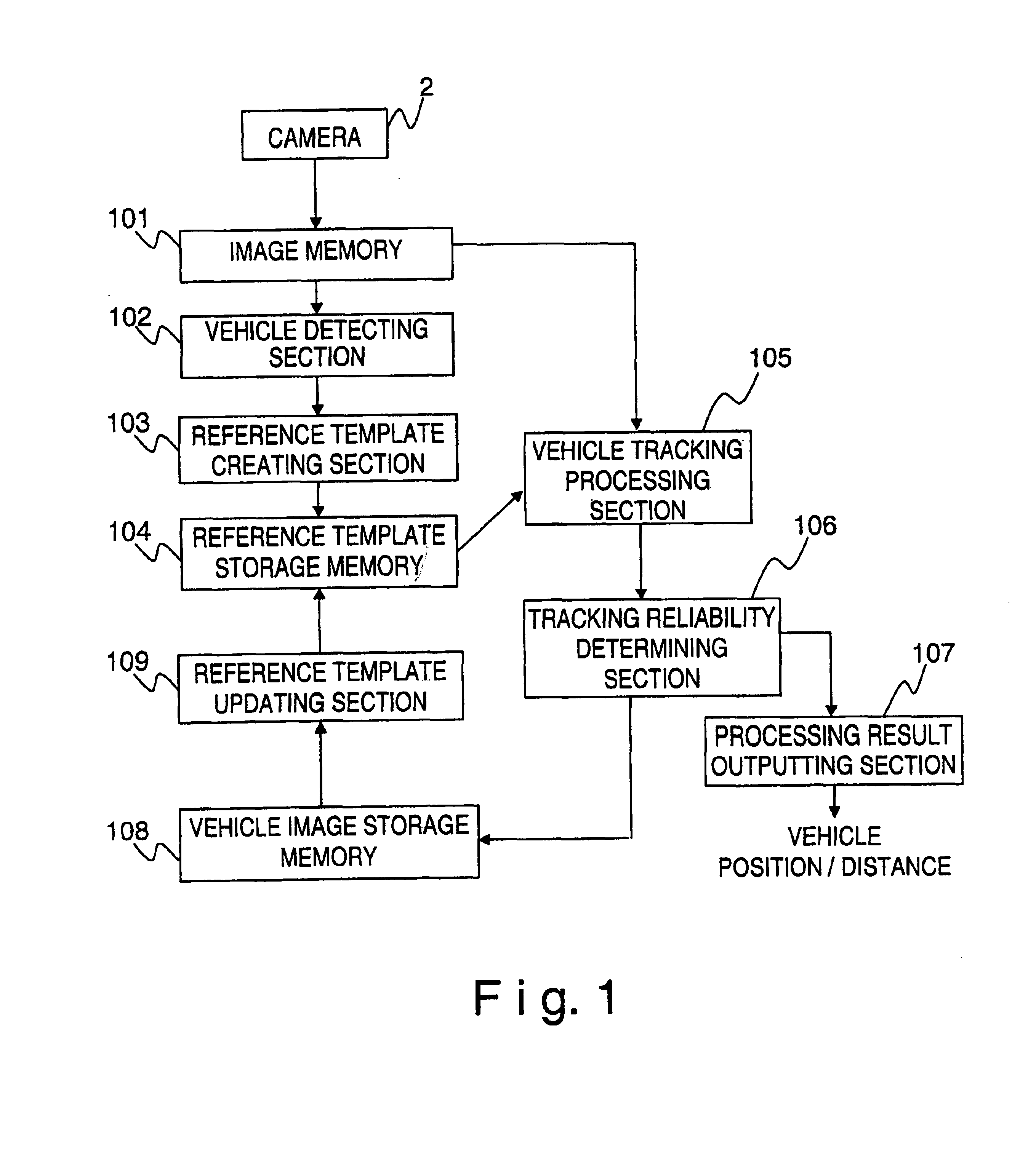
FIG. 12 is a block diagram illustrating the preceding ...


PUM


Abstract

A vehicle tracking system for a vehicle is configured to track a remote vehicle by template matching between a reference image and an input image obtained by a camera mounted on the vehicle. The position and distance of a remote vehicle is determined by calculating a position and an enlargement/reduction ratio of a portion of the input image that provide a maximum correlation value between the portion of the input image and the reference template that is greater than a threshold value. The reference template is updated by calculating a dispersion of at least one pixel of the reference template with respect to a corresponding pixel in a vehicle image extracted from the input image that provides the maximum correlation value, and by deleting the at least one pixel when the dispersion of the at least one pixel is equal to or greater than a threshold value.

Description

BACKGROUND OF THE INVENTION1. Field of the InventionThe present invention relates to a vehicle tracking system installed on a vehicle. Specifically, the present invention relates to a vehicle tracking system that tracks a vehicle in a reliable manner by using template matching. Preferably, the vehicle tracking system is a preceding vehicle tracking system that tracks a preceding vehicle.2. Background InformationOne example of a conventional vehicle tracking system using template matching is disclosed in the Japanese Laid-Open Patent Publication No. 2000-113158. This publication describes a system for tracking an object in which a reference template is defined for a vehicle detected by using image processing of an input image. Moreover, the system disclosed in the above publication detects a new position of the vehicle by finding a correlation between a newly inputted image and the reference template. If the correlation value is high, the reference template is updated to an image of ...

Claims


Application Information

Patent Timeline
IPC IPC(8): B60R21/00G01B11/00G01S1/00G06T1/00G06T7/00G08G1/16H04B7/185H04N7/18G01S3/786G01S17/931G01S19/14
CPCG01S3/7865G06K9/00791G06K9/3241G06T7/204G01S17/936G06T2207/30252G06T2207/10016G06T2207/30248G06K2209/23G06T7/248G01S17/931G06V20/56G06V10/255G06V2201/08
Inventor SHIMOMURA, NORIKO
Owner NISSAN MOTOR CO LTD
Why Eureka
Try Eureka