
Adaptive lithographic critical dimension enhancement

a critical dimension and enhancement technology, applied in the field of lithographic system and method of lithographic exposure, can solve the problems of loss of yield, cd uniformity, affecting critical dimension uniformity, etc., and achieve the effect of improving cd uniformity

Active Publication Date: 2005-03-29
ASML NETHERLANDS BV
View PDF8 Cites 62 Cited by
  • Summary
  • Abstract
  • Description
  • Claims
  • Application Information

AI Technical Summary

Benefits of technology

This patent describes systems and techniques for improving the accuracy of patterns created through a process called photolithography. By measuring the characteristics of these patterns after they have been formed, the system can determine if there any inconsistencies or unevenness in their size. If this occurs, the system will adjust its settings to fix those issues during subsequent processing steps. Ultimately, this results in more accurate and reliable pattern formation across multiple devices made from different materials.

Problems solved by technology

This patent describes a method for creating patterns on semiconductor materials using a lithographic exposure apparatus. These patterns are generated through a combination of imaging and engineering techniques. The technical problem addressed in the patent is ensuring accurate reproduction of the desired pattern on the surface of the substrate after multiple stages of pre- and post-exposure procedures, such as cleaving, etching, and measuring.

Method used


Image

  • Adaptive lithographic critical dimension enhancement
  • Adaptive lithographic critical dimension enhancement
  • Adaptive lithographic critical dimension enhancement

Examples


Embodiment Construction

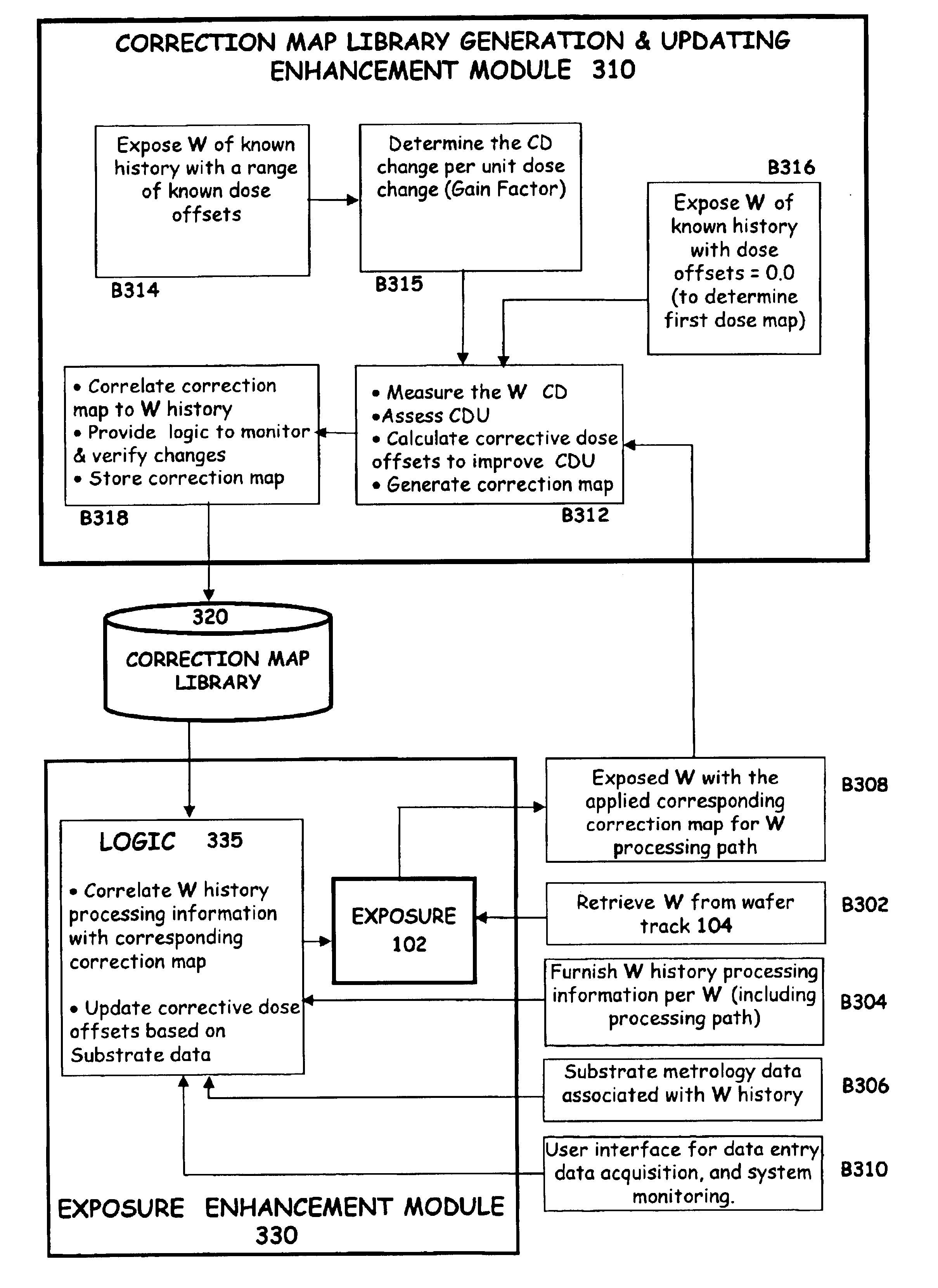
gram depicting an embodiment of the present invention;

[0029]FIGS. 4A, 4B illustrate examples of pre-exposure metrology data;

[0030]FIGS. 4C, 4D illustrate a typical dose layout used to determine the gain factor for the process and the corresponding wafer CD change per unit dose, respectively;

[0031]FIGS. 4E, 4F illustrate a typical dose layout with dose offsets set to zero and the corresponding results of a wafer CD, respectively; and

[0032]FIGS. 4G, 4H illustrate a typical optimal corrected dose layout and the corresponding result of a wafer CD, respectively.

[0033]In the figures, corresponding reference symbols indicate corresponding parts.

DETAILED DESCRIPTION

[0034]As noted above, processes that treat the substrate wafers contribute to variations in CDU that negatively affect the quality and performance of the exposed patterns. Such non-uniformities may occur across a target field, across a wafer, and between wafers. Moreover, these non-uniformities can also vary depending a variety o...


PUM


Abstract

A system, apparatus, and method for improving CD uniformity in lithographic system is presented herein. The system includes an exposure apparatus configured to expose substrates, a track apparatus that is operatively coupled to the exposure apparatus and a plurality of processing modules and apparatus. The system also includes a measuring device configured to measure attributes of the exposed and processed substrates and to assess whether the exposed and processed substrate attributes are uniform based on pre-specified substrate profile information. The system further includes a module configured to adaptively calculate corrective exposure data based on the measured attributes upon determining that said attributes are not uniform. The corrective exposure data is configured to correct for non-uniformities in the substrates by regulating the exposure dosage of the exposure apparatus. Once the substrates are assessed to achieve the desired uniformity, the substrates are exposed by the exposure apparatus in accordance with the corrective exposure data, the uniformity of the exposed substrate continues to be monitored and the dose corrections are updated as required to maintain uniformity.

Description


Claims


Application Information

Patent Timeline
Owner ASML NETHERLANDS BV
Learn More