Graphic correction method and mask making method

A reticle and pattern technology, which is applied to the photoengraving process of the pattern surface, the originals for photomechanical processing, and the instruments, etc., which can solve the problem of increasing processing time, lack of scattering strips, and difficulty in ensuring the uniformity of short scattering strips, etc. problem, to achieve the effect of improving CD uniformity and efficiency

Active Publication Date: 2022-07-19
SEMICON MFG INT (BEIJING) CORP +1
View PDF5 Cites 0 Cited by
  • Summary
  • Abstract
  • Description
  • Claims
  • Application Information

AI Technical Summary

Problems solved by technology

[0004] However, in the case of dividing long scattering strips into layers of short scattering strips, it is difficult to ensure the uniformity of the short scattering strips at the line ends of the pattern to be cut
In addition, in the case of directly generating short scatter bars by shortening the maximum length of scatter bars, missing scatter bars may occur in the tile boundary area (Tile Boundary Area), and the missing scatter bars will cause the main The CD of the pattern changes
While missing scatter bars can be checked and repaired by setting a Clean Up step, this step adds significantly to the processing time of the overall process

Method used


Image

  • Graphic correction method and mask making method
  • Graphic correction method and mask making method
  • Graphic correction method and mask making method

Examples


Embodiment Construction

[0029] The following description provides specific application scenarios and requirements of the present application, and is intended to enable those skilled in the art to make and use the contents of the present application. Various partial modifications to the disclosed embodiments will be readily apparent to those skilled in the art, and the generic principles defined herein may be applied to other embodiments and without departing from the spirit and scope of the present disclosure. application. Thus, the present disclosure is not to be limited to the embodiments shown, but is to be accorded the widest scope consistent with the claims.

[0030] The technical solutions of the present invention will be described in detail below with reference to the embodiments and the accompanying drawings.

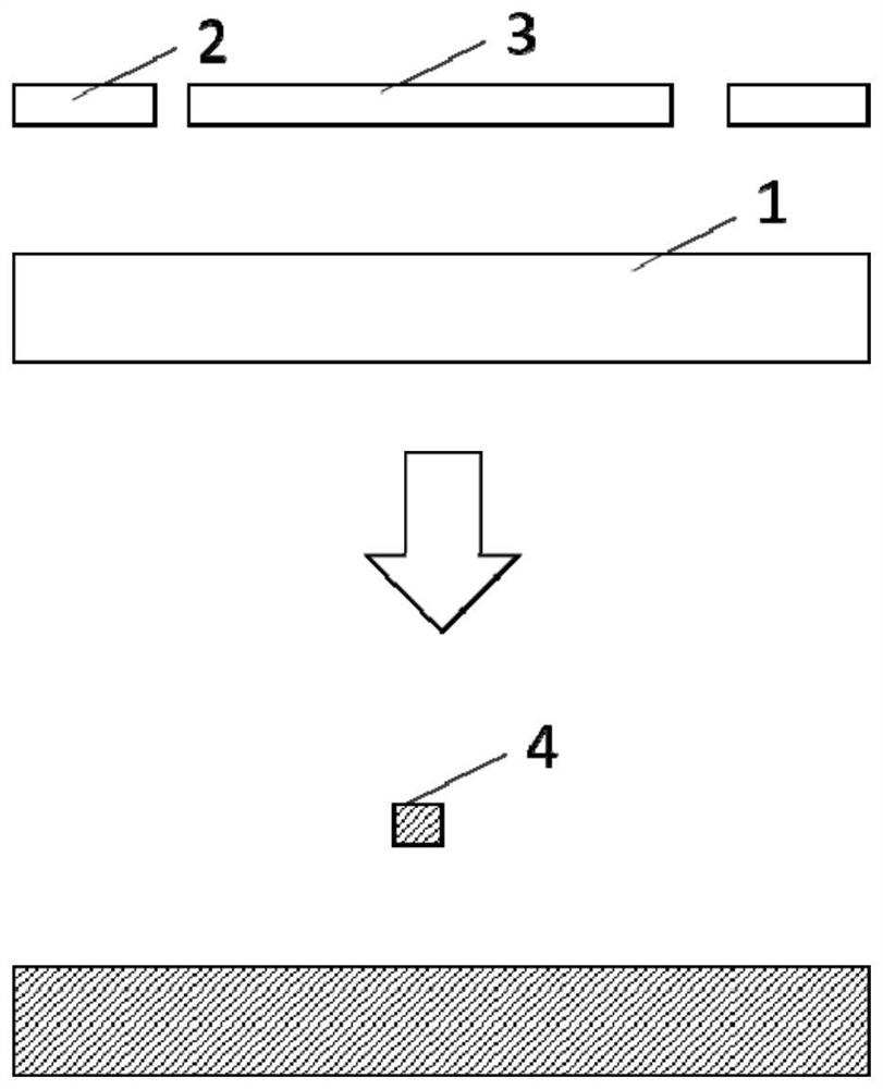
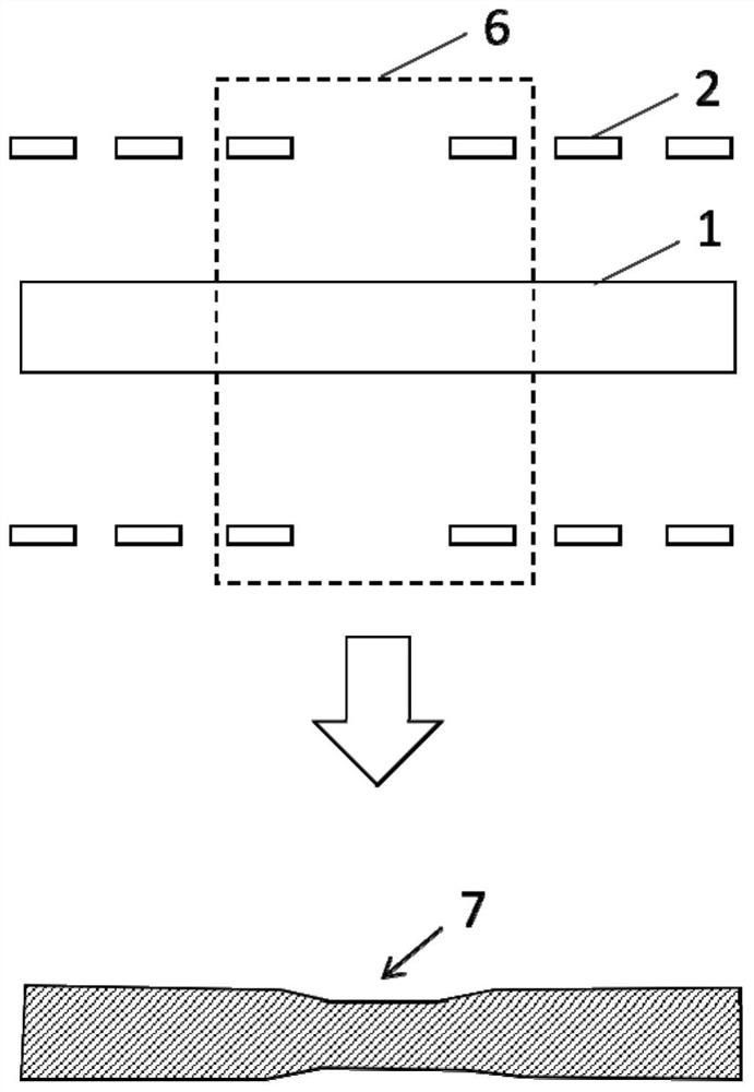
[0031] In the target pattern, there are usually both densely distributed patterns (such as 1:1 equidistant lines) and sparse patterns (such as independent lines), especially the desig...


PUM


Abstract

The present application discloses a method for modifying graphics, the method includes: providing a target pattern, the target pattern includes a first layer pattern and a second layer pattern, the first layer pattern includes a plurality of first graphics extending along a first direction, the first layer pattern The two-layer pattern includes a second pattern extending along the second direction, and the second pattern spans a plurality of first patterns; an initial scattering stripe pattern is set in the second layer pattern, and the initial scattering stripe pattern is located at the position of the second pattern along the first direction. On the side part, the initial scattering bar pattern spans a plurality of first patterns; the overlapping patterns of the plurality of first patterns and the initial scattering bar pattern are obtained; and each overlapping pattern is extended along both sides parallel to the second direction, so that the overlapping patterns are overlapped. The graphics form auxiliary graphics that are separate from each other. The present application also discloses a method for making a mask. The modification method of the pattern disclosed in this application improves the CD uniformity of the actual cutting position.

Description

technical field [0001] The present application relates to the field of semiconductor technology, and in particular, to a method for correcting a pattern and a method for manufacturing a mask. Background technique [0002] As the semiconductor technology node reaches 5 nm and below, the requirements for the uniformity (Uniformity) of the critical dimension (CD) of the main pattern are getting higher and higher. If there are sparse patterns in the main pattern, it will result in poor CD uniformity after development of the main pattern. To avoid this, you can add some small Scattering Bars around the sparse pattern to make the sparse pattern look like a dense pattern from an optical angle. [0003] As the critical dimension is reduced to 5 nm and below, Positive Tone Development (PTD) has been unable to achieve the required resolution accuracy. Therefore, Negative Tone Development (NTD) can be used to perform photolithography on the cut layer. However, due to the greater res...

Claims


Application Information

Patent Timeline
Patent Type & Authority Patents(China)
IPC IPC(8): G03F1/72
CPCG03F1/72
Inventor 覃柳莎舒强王占雨张迎春
Owner SEMICON MFG INT (BEIJING) CORP
Why Eureka
Try Eureka