Method of making an acoustic wave resonator

a resonator and acoustic wave technology, applied in the field of acoustic resonators, can solve the problems of large electrical losses at microwave frequencies of ferromagnetic materials, and achieve the effect of not significantly affecting the electrical resistance of electrodes

a resonator and acoustic wave technology, applied in the field of acoustic resonators, can solve the problems of large electrical losses at microwave frequencies of ferromagnetic materials, and achieve the effect of not significantly affecting the electrical resistance of electrodes

US6874212B2Inactive Publication Date: 2005-04-05AVAGO TECH INT SALES PTE LTD

Image

  • Method of making an acoustic wave resonator
  • Method of making an acoustic wave resonator
  • Method of making an acoustic wave resonator

Examples


Embodiment Construction

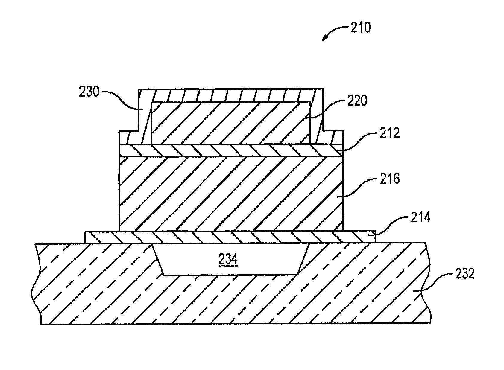
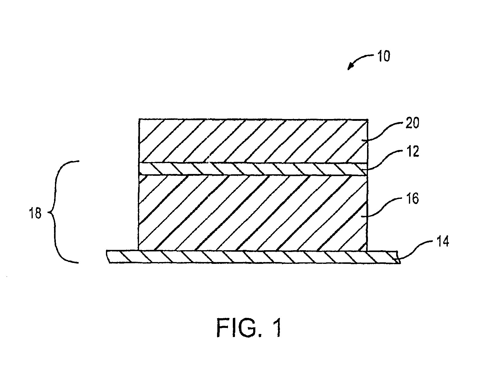
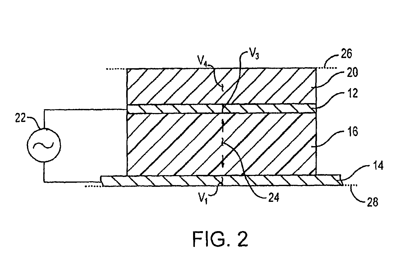
Referring to FIG. 1, an exemplary embodiment of an acoustic resonator 10 includes a pair of opposed electrodes 12 and 14. Between the opposed electrodes 12 and 14 is a piezoelectric body 16, forming an electrode-piezoelectric stack 18. The stack 18 is typically referred to as a thin film bulk acoustic resonator (FBAR).

Disposed adjacent to the stack 18 is a compensator body 20 that facilitates stabilization of the resonant frequency of the acoustic resonator 10 when subjected to temperature variations. This is achieved by forming the compensator body 20 from one or more materials having a positive temperature coefficient of frequency. The positive temperature coefficient of frequency compensates for the negative temperature coefficient of frequency of the materials from which the electrode-piezoelectric stack 18 is formed.

Typically, the piezoelectric body 18 is formed from any piezoelectric material that provides a reasonably high electromechanical coupling constant and low dielectri...


PUM

PropertyMeasurementUnit
Fractionaaaaaaaaaa
Fractionaaaaaaaaaa
Temperatureaaaaaaaaaa

Abstract

A method of fabricating an acoustic resonator includes forming a ferromagnetic compensator, such as one comprised of a nickel-iron alloy, which at least partially offsets temperature-induced effects introduced by an electrode-piezoelectric stack. The compensator has a positive temperature coefficient of frequency, while the stack has a negative temperature coefficient of frequency. By properly selecting the thickness of the compensator, temperature-induced effects on resonance may be neutralized. Alternatively, the thickness can be selected to provide a target positive or negative composite temperature coefficient of frequency. In order to prevent undue electromagnetic losses in the ferromagnetic compensator, a metallic flashing layer may be added to at least partially enclose the compensator.

Description


Claims


Application Information

Patent Timeline
05 Apr 2005
Publication
US6874212B2