Hydraulic piston locking device

Inactive Publication Date: 2005-04-05
HUNT MICHAEL H +1
View PDF28 Cites 17 Cited by
  • Summary
  • Abstract
  • Description
  • Claims
  • Application Information

AI Technical Summary

Benefits of technology

An important object of the present invention is to provide an improved locking device for use with heavy machinery that prevents the movement of a hydraulic piston rod and thus prevents the theft of the ma

Problems solved by technology

Heavy machinery such as such as loaders, backhoes, skid steer loaders, crawlers, graders, articulated loaders, trenchers, dozers, and the like are typically parked on the job site throughout the course of a construction project because the effort to transport the equipment to a secure site is expensive and time-consuming.
The machinery is susceptible to theft and vandalism.
Equipment theft from construction sites is a significant problem.
The machinery is expensive to replace if stole

Method used


Image

  • Hydraulic piston locking device
  • Hydraulic piston locking device
  • Hydraulic piston locking device

Examples


Example

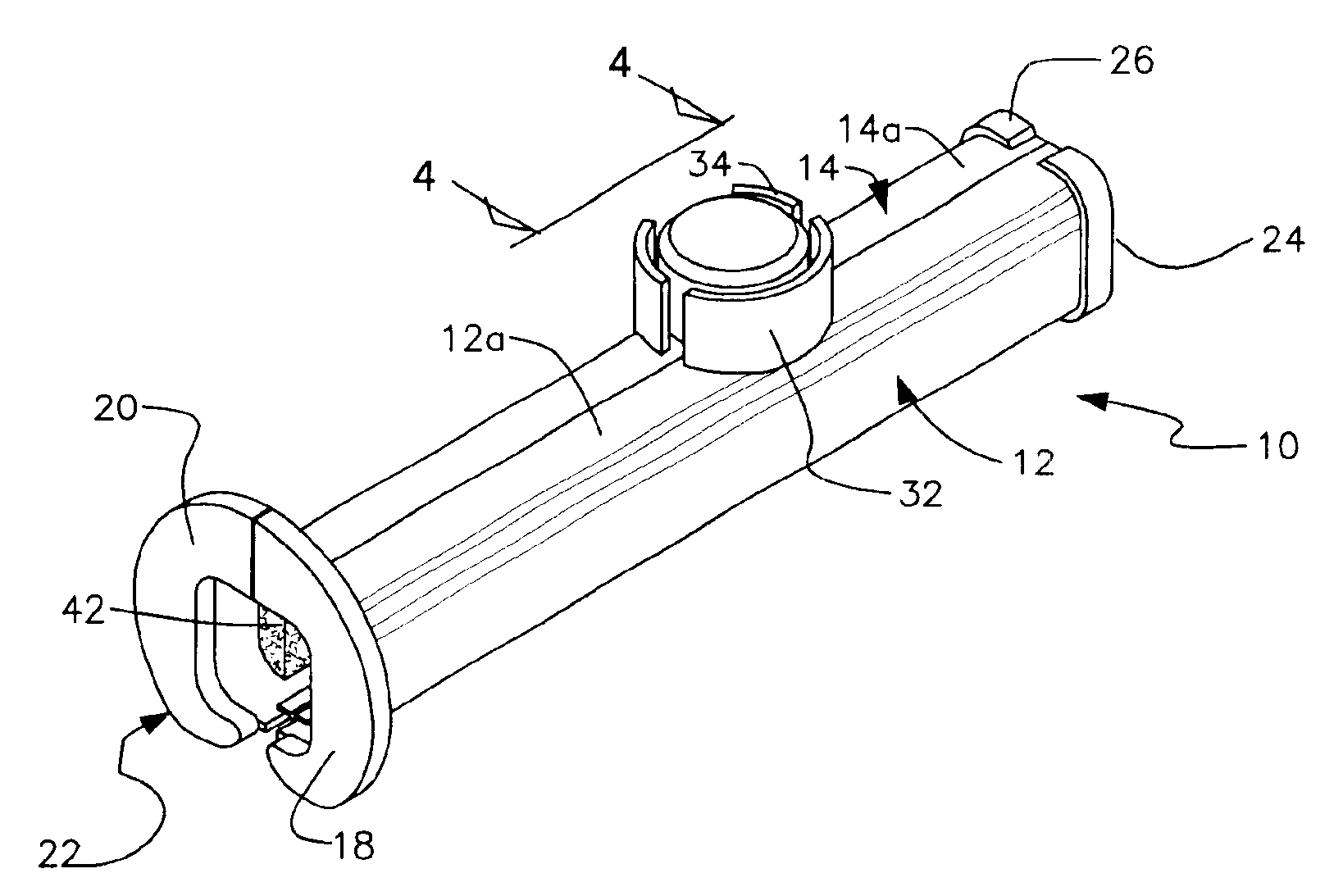
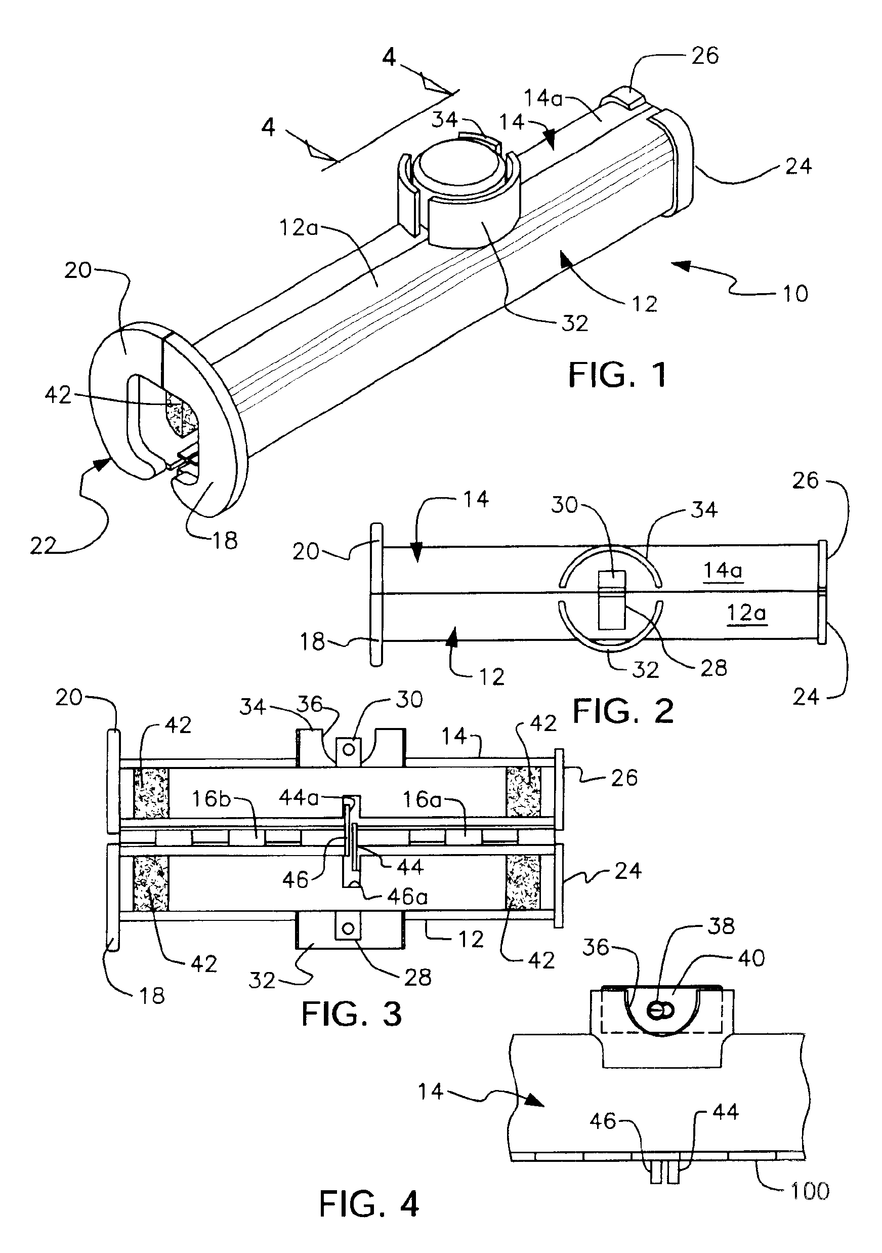
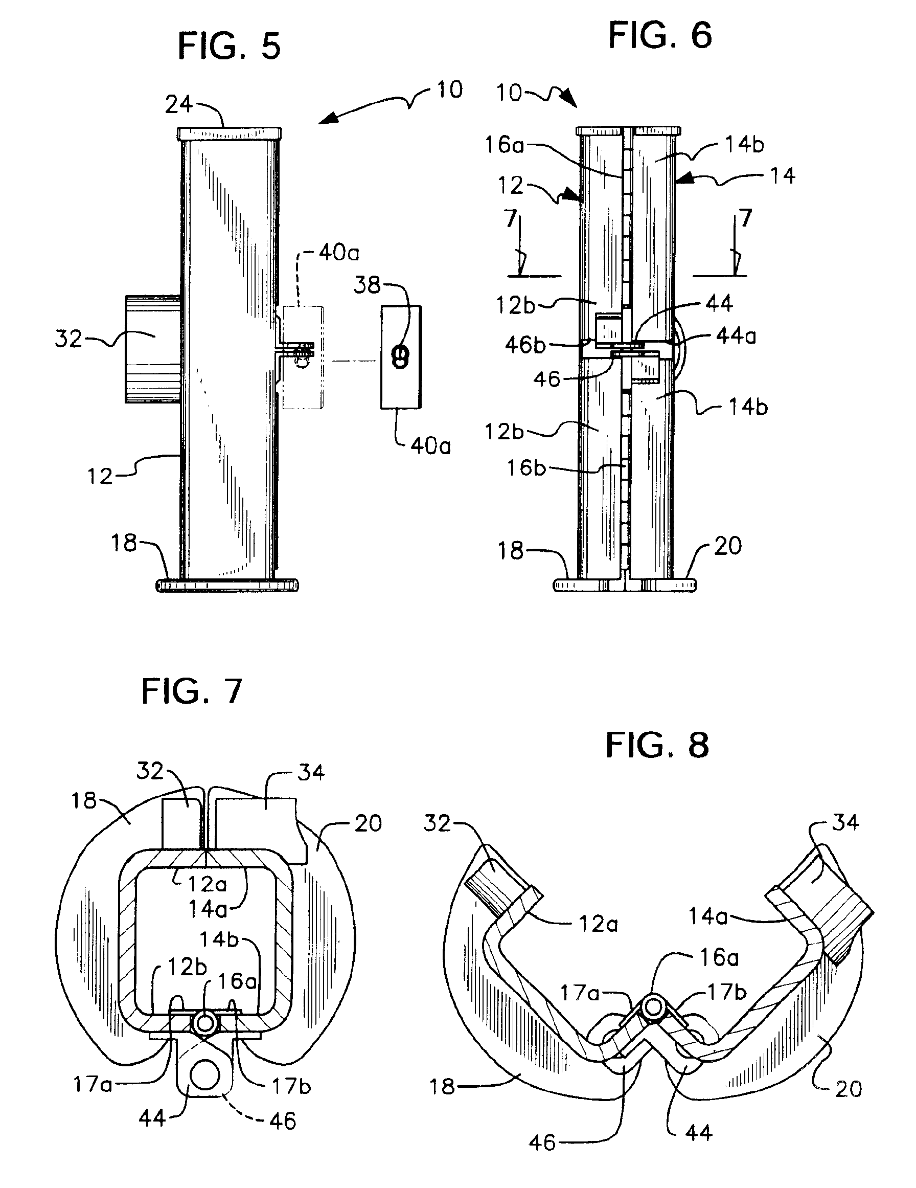
Referring now to FIGS. 1 and 2, it will there be seen that the reference numeral 10 denotes the novel locking device as a whole. Device 10 will be known commercially as the SleevLock™ theft-deterrent apparatus or locking device.

Locking device 10 includes first sleeve part 12 and second sleeve part 14. Each of said sleeve parts is channel shaped so that when said parts are positioned in confronting relation to one another, they collectively form a hollow sleeve. Although both sleeve parts are depicted as having a generally square “U” shape in transverse cross-section so that they collectively form an elongate square sleeve when disposed in confronting relation to one another, each of said sleeve parts could also have a semi-circular shape in transverse cross-section so that they collectively form a cylinder when so disposed. Nor is the invention limited to hollow sleeves of square or cylindrical cross-section; a machine designer of ordinary skill may select numerous other operable sh...


PUM


Abstract

A device for locking a piston rod of a hydraulic piston and cylinder assembly in an extended condition so that mobile construction equipment or other heavy machinery cannot be driven from a job site. The locking device is placed in ensleeving relation to an extended piston rod between a proximal hydraulic cylinder and a distal bearing point to prevent retraction of the piston rod. The device has a hollow sleeve configuration formed of confronting first and second sleeve parts that are hingedly connected to one another. A first lock secures the first and second sleeve members to one another along a longitudinally extending parting line. A second lock is opposed to the first lock and prevents hinged movement of the first and second sleeve parts relative to one another even if the first lock is defeated. The device is adaptable to a variety of hydraulic piston and cylinder assemblies.

Description

BACKGROUND OF INVENTION1. Field of the InventionThis invention relates, generally, to anti-theft devices. More particularly, it relates to a device that locks an extended hydraulic cylinder so that it cannot move.2. Description of the Prior ArtHeavy machinery such as such as loaders, backhoes, skid steer loaders, crawlers, graders, articulated loaders, trenchers, dozers, and the like are typically parked on the job site throughout the course of a construction project because the effort to transport the equipment to a secure site is expensive and time-consuming. The machinery is susceptible to theft and vandalism.Equipment theft from construction sites is a significant problem. The machinery is expensive to replace if stolen.Devices that lock steering wheels offer little protection because such devices are easily cut off with a hacksaw or other suitable cutting tool. Other locking devices can be burned or pried off.What is needed, then, is a locking device that is highly resistant to...

Claims


Application Information

Patent Timeline
IPC IPC(8): E05B67/36E05B67/00E05B67/38E02F9/24
CPCE02F9/24E05B67/36E05B67/383Y10T70/40Y10T70/409Y10T70/411Y10T70/5642
Inventor HUNT, MICHAEL HSMITH, PRESTON E
Owner HUNT MICHAEL H
Why Eureka
Try Eureka