Plug valve

a plug valve and valve body technology, applied in the direction of plug valves, valve arrangements, mechanical equipment, etc., can solve the problem of not achieving the effect of sealing

Inactive Publication Date: 2005-04-05
SMC CORP
View PDF4 Cites 30 Cited by
  • Summary
  • Abstract
  • Description
  • Claims
  • Application Information

AI Technical Summary

Benefits of technology

A general object of the present invention is to provide a plug valve which makes it possible to prevent

Problems solved by technology

When the seal member is damaged, the fluid leak

Method used


Image

  • Plug valve
  • Plug valve
  • Plug valve

Examples


second embodiment

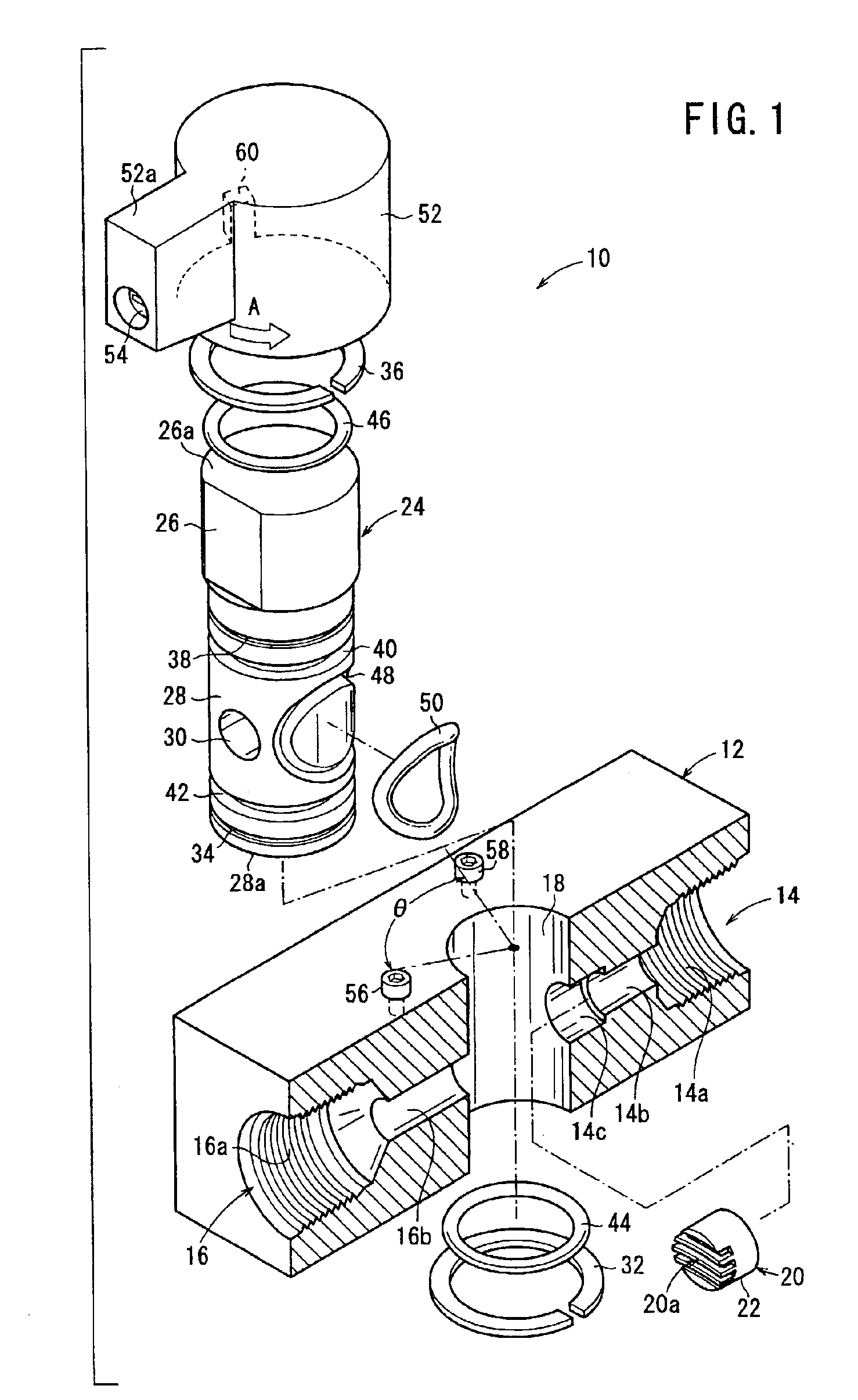
FIG. 7 shows a schematic structure of a plug valve 10a according to a

In FIG. 7, the components that are the same as the components of the plug valve 10 shown in FIG. 1 are designated by the same reference numeral, detailed explanation thereof will be omitted. The further following embodiments will be described in the same manner as described above.

In FIG. 7, an annular buffer member 64 is provided at the back of the seal-retaining member 20 (on the side of the first passage 14). The buffer member 64 absorbs any dimensional change brought about by the difference in temperature and contacts the main plug body 24 with an appropriate force, so that the O-ring 50 is prevented from excessively pressing by the main plug body 24.

third embodiment

FIG. 8 shows a schematic structure of a plug valve 70 according to a

As shown in FIG. 10, a seal-retaining member 72 made of resin includes a cylindrical section 72a and a flange 72b. The cylindrical section 72a is fitted to the reduced diameter section 14b, and the flange 72b is engaged with the expanded diameter section 14c.

The flange 72b of the seal-retaining member 72 abuts against an end surface of a spacer 76 made of resin which is fitted to the expanded diameter section 14c. The seal-retaining member 72 is attached to the reduced diameter section 14b. As shown in FIG. 8, the seal-retaining member 72 and the spacer 76 are pressed, for example, by forcible insertion or screw engagement of the spacer 76 or an unillustrated joint which is attached from the outside of the main valve body 12, i.e., into the screw hole 14a and which is screwed with the screw hole 14a.

In the plug valve 70 according to the third embodiment, the seal-retaining member 72 is pressed by the spacer 76 so ...

fourth embodiment

FIG. 9 shows a schematic structure of a plug valve 70a according to a

In FIG. 9, an annular buffer member 78, which has a large diameter in cross section, is interposed between the seal-retaining member 72 and the spacer 76, and the spacer 76 presses the buffer member 78 to prevent the O-ring 50 (see FIG. 1) from projecting.


PUM


Abstract

A main valve body has a first passage, a second passage, and an opening which intersects the first passage and the second passage. A main plug body is rotatably inserted into the opening, and has an upper section into which a handle is inserted, and a lower section having a through-hole. An O-ring is seated on an annular groove which is provided in the vicinity of the through-hole. A seal-retaining member for preventing the O-ring from projecting is fitted to an expanded diameter section of the first passage. One end of the seal-retaining member tightly contacts an end surface of the expanded diameter section. A curved surface corresponding to an inner circumferential surface of the opening is formed at the other end of the seal-retaining member.

Description

BACKGROUND OF THE INVENTION1. Field of the InventionThe present invention relates to a plug valve which a fluid flows through or is interrupted by. The plug valve is capable of reliably preventing the fluid from leakage during the interruption.2. Description of the Related ArtConventionally, a plug valve comprises a main valve body and a plug. The valve body is provided with a first passage and a second passage having their axes coincident with each other, and includes a columnar opening disposed between the first passage and the second passage. The plug is rotatably attached to the opening.The plug valve has a through-hole penetrating therethrough in a direction substantially coincident with the axial direction of the first and second passages. Accordingly, the plug is constructed such that the fluid flows from the first passage through the through-hole to the second passage.The plug is rotatable from a communication position at which the through-hole provided in the opening of the...

Claims


Application Information

Patent Timeline
IPC IPC(8): F16K5/00F16K5/04
CPCF16K5/04Y10S251/904Y10S251/90
Inventor AOSHIMA, HIROAKITOZAKI, TAKASHI
Owner SMC CORP
Why Eureka
Try Eureka