Ink jet printing apparatus and ink jet printing method for forming an image on a print medium

a printing apparatus and ink jet technology, applied in the field of ink jet printing apparatus, can solve the problems of additional density variation, failure to eliminate, degradation of image quality, etc., and achieve the effect of preventing a degradation of image quality and high speed

Inactive Publication Date: 2005-04-05
CANON KK
View PDF11 Cites 105 Cited by
  • Summary
  • Abstract
  • Description
  • Claims
  • Application Information

AI Technical Summary

Benefits of technology

The present invention has been accomplished to overcome the problems experienced with the conventional techniques described above and to provide a printing apparatus and a printing method capable of forming a high-resolution image at high speed while preventing a degradation of image quality due to white stripes and density variations.

Problems solved by technology

This in turn results in density variations in the image formed, degrading the image quality.
However, even with this multipass printing method it has been confirmed that the density variations may fail to be eliminated at all depending on a print duty of each main scan and that in a half-tone printing additional density variations occur.
It is, however, feared that reducing the amount of ink ejected per dot may cause problems (deviation of dot landing positions and ink ejection instability).
Further, in the techniques described in the above official gazettes, because the paper feed is controlled at variable pitches, as opposed to a normal constant pitch, it is feared that the throughput may deteriorate.

Method used


Image

  • Ink jet printing apparatus and ink jet printing method for forming an image on a print medium
  • Ink jet printing apparatus and ink jet printing method for forming an image on a print medium
  • Ink jet printing apparatus and ink jet printing method for forming an image on a print medium

Examples


second embodiment

Next, the ink jet printing apparatus and method according to this invention will be described.

According to the second embodiment, in the same pass area E which is printed in a plurality of the main scans, the divided areas e1, e2 corresponding to the ends of the print head have their printing duties set smaller than those of the divided areas on the inner side of the ends of the print head.

To describe in more detail, in the conventional ordinary 4-pass printing (division number is 1) each nozzle column is divided into four nozzle groups corresponding to the four pass areas E and the printing duty of each pass area E is set at 25%, as shown in FIG. 17A. In this embodiment, as shown in FIG. 17B, each pass area E is divided into two split areas e1, e2 and the printing duties of the split areas e1, e2 corresponding to the nozzles n at the ends of the print head H1001 are set at lower values (6.25%) than those of other split areas e1, e2. The printing duties in each pass area range from ...

first embodiment

With the printing duties at the ends of the print head set at lower values, the end nozzle dot deflection in the image can only occur at a very low frequency of one in 16 dots. As a result, the end nozzle dot deflections are not perceived as a white stripe. Hence, not only can the banding in the image be eliminated as in the first embodiment but the white stripes due to the end nozzle dot deflections can also be eliminated, thus forming an image of higher quality.

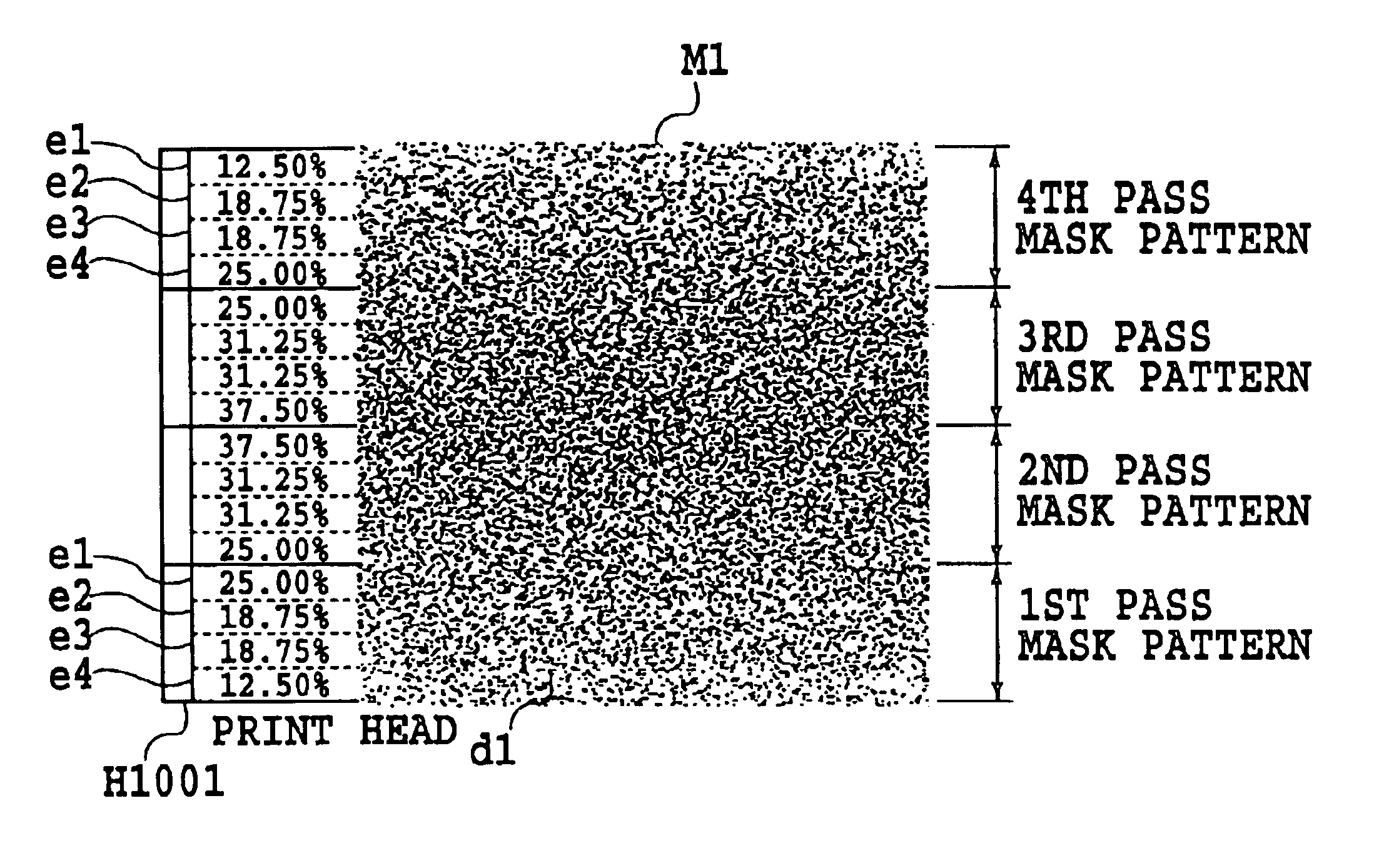
While the second embodiment has been explained by taking up an example case where the pass area E is divided in two, the pass area may be divided into three or more. For example, a single pass area E may be divided into four areas e1, e2, e3, e4 as shown in FIGS. 20A and 20B. In this case, the printing duties of the divided areas e1, e4 at the ends of the print head are set at relatively low values of 12.5%, with the printing duties of other divided areas set to increase progressively as they approach the center of the prin...

third embodiment

Next, the ink jet printing apparatus and method according to the invention will be described.

In the first and second embodiments, when the cycle of random number is short, there is a problem that a repetitive pattern appears on the output image and that when a uniform random number is used, a granularity may deteriorate due to a low frequency component of the random number. To cope with this problem, the present invention according to the third embodiment is characterized by a moving means for moving the print head having a plurality of print elements relative to the print medium. Further, in a printing apparatus in which the print head is divided into a plurality of nozzle groups and one and the same area on the print medium is scanned a plurality of times by the same divided nozzle group or different groups of the print head to form a thinned out image in each scan according to a thinning out pattern to complete an image in that area of the print medium, the invention is also char...


PUM


Abstract

An apparatus and method are provided to enable high speed printing of an image with high resolution while suppressing degradation of image quality due to white stripes and density variations. In an ink jet printing apparatus using a multi-pass printing system, the same scan print area is divided at a predetermined pitch and the printing duties of the divided areas determined by the thinning out mask pattern are set to different values. In regard to the same scan print area formed by a plurality of the main scans, the divided areas corresponding to the ends of the print head have their printing duties set smaller than those of the divided areas on the inner side of the ends of the print head.

Description

This application is based on Japanese Patent Application Nos. 11-237325 (1999) filed Aug. 24, 1999, and 2000-216687 filed Jul. 17, 2000, the contents of which are incorporated hereinto by reference.BACKGROUND OF THE INVENTION1. Field of the InventionThe present invention relates to an ink jet printing apparatus that ejects ink from nozzles for printing, and more particularly to a printing apparatus of a so-called multipass system which uses a print head having a plurality of nozzle groups each consisting of a plurality of nozzles and performs a plurality of main scans over the same main scan print area of a predetermined print medium by using different nozzle groups to form different thinned out images during the main scans according to thinned out mask patterns associated with the respective scans to complete an image. More specifically, the present invention concerns a reduction in image degrading factors such as density variations and white stripes.In addition to general printing...

Claims


Application Information

Patent Timeline
Patent Type & Authority Patents(United States)
IPC IPC(8): B41J2/505G06K15/02G06K15/10
CPCG06K15/105B41J2/5058
Inventor MAEDA, TETSUHIROTAJIKA, HIROSHIUSHIRODA, ATSUSHIFUJITA, MIYUKIKONNO, YUJIKAWATOKO, NORIHIROOGASAHARA, TAKAYUKIEDAMURA, TETSUYA
Owner CANON KK
Why Eureka
Try Eureka