Light brightness changeable electroluminescent device

Inactive Publication Date: 2005-04-05
HSU TAI PING
View PDF15 Cites 57 Cited by
  • Summary
  • Abstract
  • Description
  • Claims
  • Application Information

AI Technical Summary

Benefits of technology

The other objective of the present invention is to provide an electroluminescent device including one or more batteries that may

Problems solved by technology

However, the light bulbs occupy a great-size or volume that may greatly increase the volume of the light devices and that is adverse for both transportation and storing purposes.
However, the electroluminescent light materials are directly energized to generate lights, such that the patterns are fixed or predetermined and may not be changed to different

Method used


Image

  • Light brightness changeable electroluminescent device
  • Light brightness changeable electroluminescent device
  • Light brightness changeable electroluminescent device

Examples


Embodiment Construction

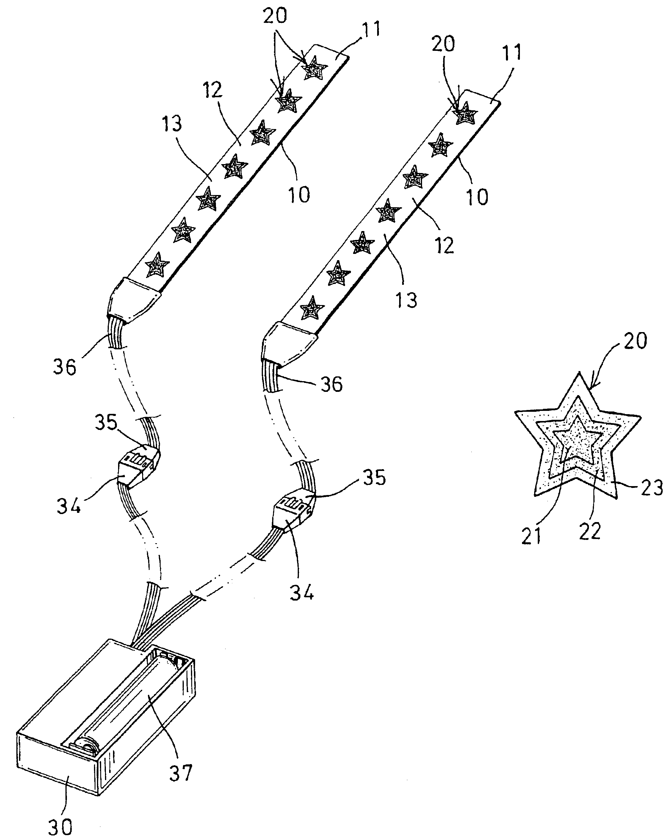
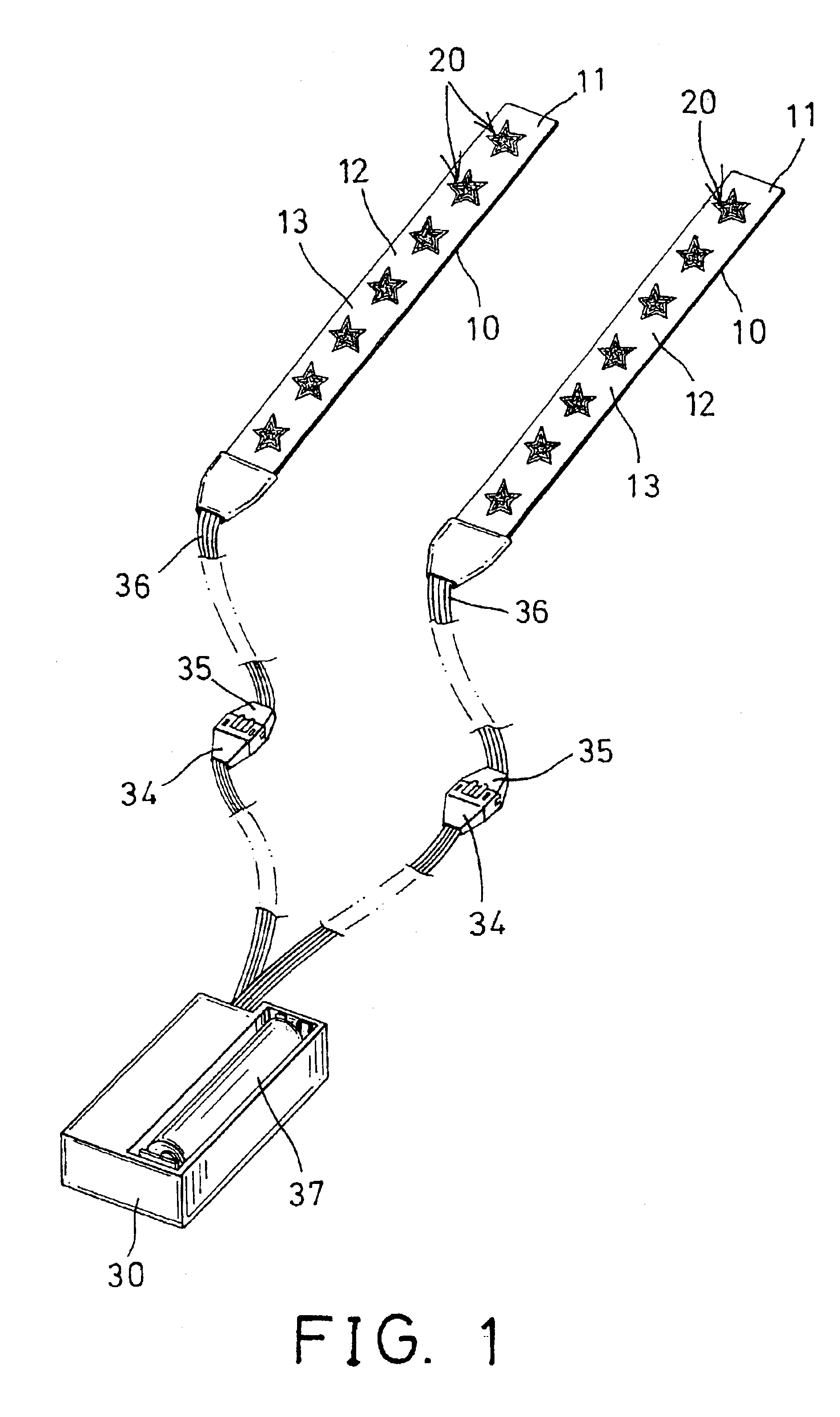
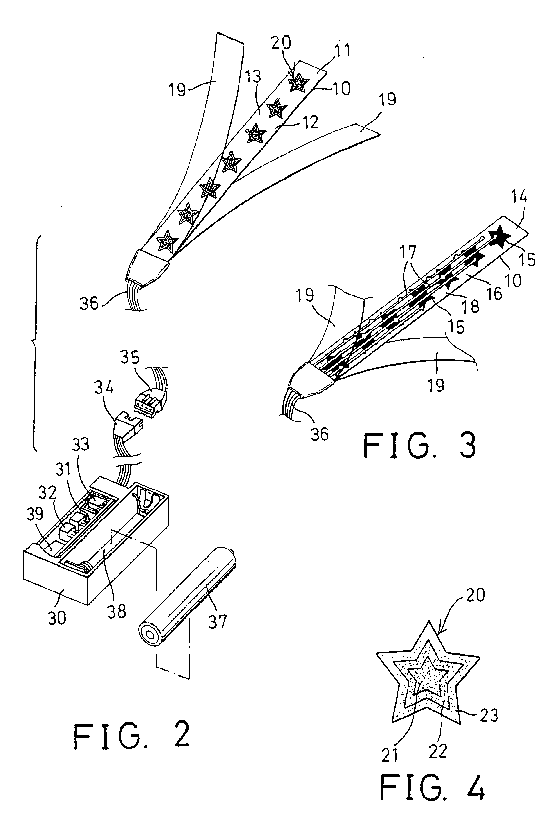
Referring to the drawings, and initially to FIGS. 1-3, an electroluminescent device in accordance with the present invention comprises one or more base panels 10 preferably made of electrically insulated and / or transparent or semi-transparent materials, such as poly vinyl chloride (PVC) materials, or other synthetic materials. The base panels 10 each may be formed into various shapes or contours for attaching onto various objects, such as shoes, bags, backpacks, etc.

The base panel 10 includes one surface, such as the upper surface 11 having one or more patterns 20 applied thereon, and having one or more spaces or areas 12 formed or defined between the patterns 20, and preferably (but not necessarily) applied with an opaque material or layer or painting 13 for allowing light to emit through the patterns 20 only. The patterns 20 may be formed into various kinds of shapes or contours, such as the star-shape as shown in the drawings.

As shown in FIG. 3, the base panel 10 includes an oppo...


PUM


Abstract

An electroluminescent device includes one or more electroluminescent laminates attached onto a bottom surface of a base panel and one or more patterns attached onto an upper surface of the base panel. The patterns each may include two or more spaces having different material of different brightnesses to generate light of different brightness through the different materials when the electroluminescent laminate is energized. The patterns may include one or more outer peripheral spaces formed around the other inner peripheral surfaces, to generate light of different brightnesses.

Description

BACKGROUND OF THE INVENTION1. Field of the InventionThe present invention relates to an electroluminescent device, and more particularly to an electroluminescent device having light changeable structure or having lights that may be changed to different brightnesses.2. Description of the Prior ArtVarious kinds of typical light devices have been developed for attaching onto various objects, such as shoes, cycles, etc., in order to generate warning or decorative lights or patterns. The typical light devices comprise a number of light bulbs or the like for generating lights. However, the light bulbs occupy a great-size or volume that may greatly increase the volume of the light devices and that is adverse for both transportation and storing purposes.The other typical electroluminescent devices have also been developed for attaching onto various objects, and comprise electroluminescent light panel segments or materials that may be arranged in planar structure and that may occupy a relati...

Claims


Application Information

Patent Timeline
IPC IPC(8): A43B3/00
CPCA43B3/0005A43B3/001Y10S362/802F21Y2101/02F21Y2115/20A43B3/36A43B3/34
Inventor HSU, TAI PING
Owner HSU TAI PING
Why Eureka
Try Eureka