Multiple port catalytic combustion device and method of operating same

a combustion device and multi-port technology, applied in the direction of combustion types, lighting and heating apparatus, furnaces, etc., can solve the problems of combustion device damage, combustion device damage, and effluent exhausted from the power system, and achieve the effect of reducing the cost of operation

Inactive Publication Date: 2005-04-05
GENERAL MOTORS COMPANY
View PDF15 Cites 22 Cited by
  • Summary
  • Abstract
  • Description
  • Claims
  • Application Information

AI Technical Summary

Benefits of technology

The present invention is directed to a catalytic combustion device that diminishes and / or eliminates the need for a flame arrestor within the combustion device. This is accomplished by splitting the H2 containing effluent exhausted by the power system into a plurality of flows and injecting the plurality of flows in multiple locations along the combustion device. The injection of the flows are controlled so that the fuel mixture within the combustion device is at a concentration that has an autoignition temperature that is above the operating temperature of the various sections of the combustion device. The present invention also provides a method of operating such a combustion device. The invention further discloses a method of starting up the combustion device when the flow of H2 within the anode effluent is not sufficient to meet the heat demand placed on the combustion device.

Problems solved by technology

The creation of electrical power within the power system results in effluents that are exhausted from the power system.
Additionally, because the amount of H2 contained within the effluent varies, the amount of reaction occurring in any particular area within the combustion device can also vary and result in hot spots or locations of excessive heat that can damage the combustion device.
When autoignition of the fuel mixture within some areas occurs, the combustion device typically is damaged and possibly completely destroyed.
While the use of the high density foam structure may prevent flame propagation to an undesirable area in the combustion device, the high density foam structure produces a significant pressure drop as the fuel mixture flows through the high density foam structure.
The pressure drop is undesirable because it may require the effluents flowing into the combustion device to pass through additional equipment to increase the pressure of the effluents prior to entering the combustion device so that adequate pressure and flow of the effluents through the combustion device is achieved.
The extra equipment to pressurize the fuel flow increases the complexity and cost of the system within which the combustion device is employed.

Method used


Image

  • Multiple port catalytic combustion device and method of operating same
  • Multiple port catalytic combustion device and method of operating same
  • Multiple port catalytic combustion device and method of operating same

Examples


Embodiment Construction

The following description of the preferred embodiments is merely exemplary in nature and is in no way intended to limit the invention, its application, or uses.

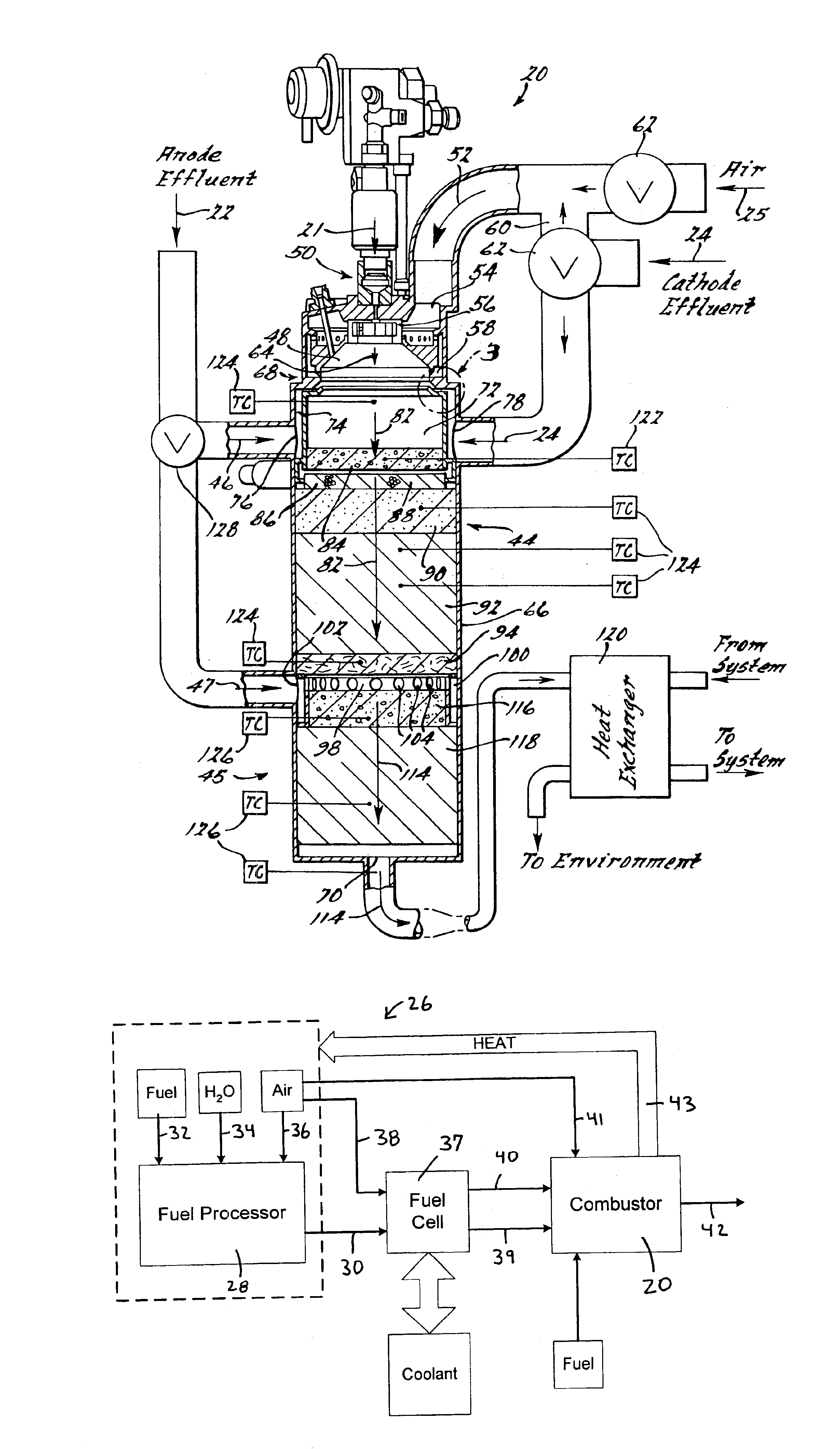
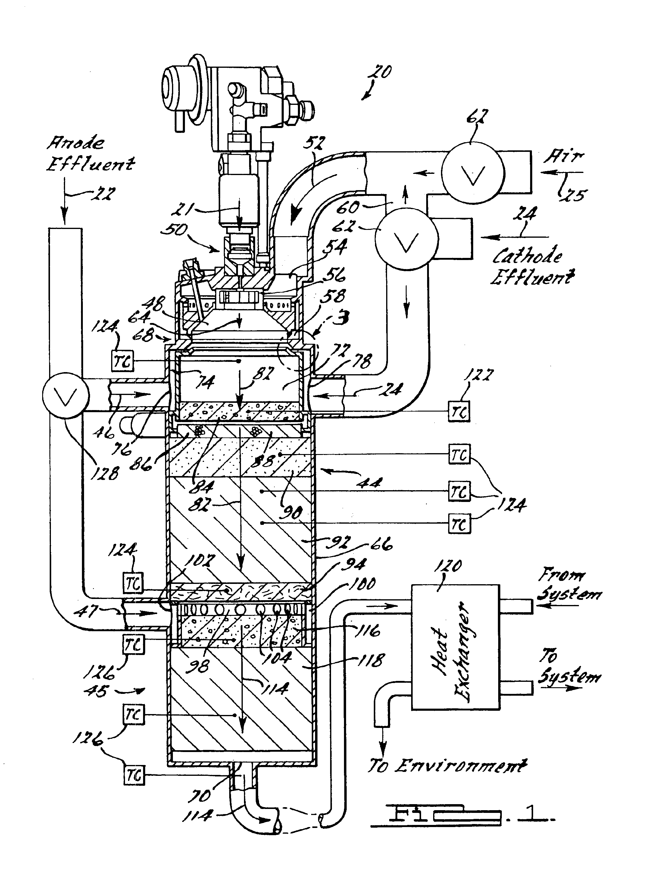
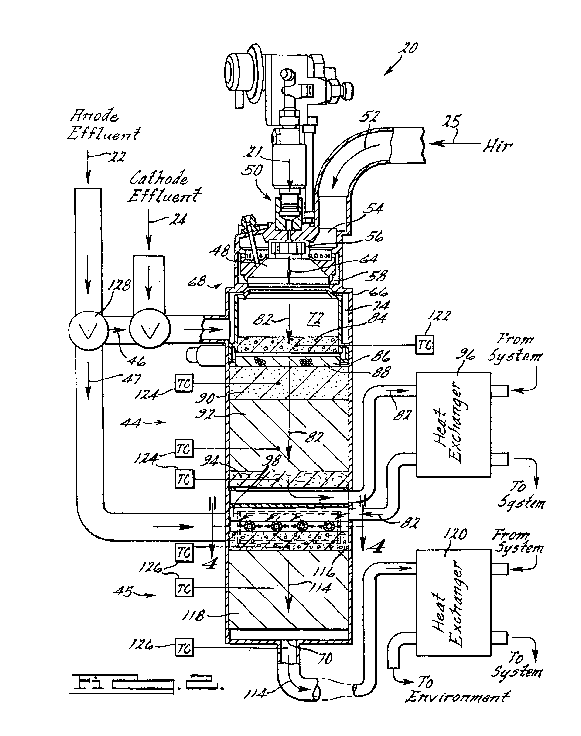
Shown in FIG. 1 is a combustor 20 in accordance with the principles of the present invention can catalytically combust liquid fuel 21, anode effluent 22, or liquid fuel 21 in combination with anode effluent 22. The combustor 20 is designed to combust liquid fuel 21 and / or anode effluent 22 catalytically with an oxidant, such as cathode effluent 24 and / or air 25 while maintaining a controlled combustion process. By controlling the combustion process, the temperature throughout the combustor 20 can be controlled, different heat loads placed on the combustor 20 can be met, and flammable or thermal combustion can be minimized and / or prevented, as will be described below. To accomplish this, the combustor 20 is divided into a plurality of stages in which catalytic combustion occurs. Each stage receives a different fuel flow so tha...


PUM

PropertyMeasurementUnit
temperatureaaaaaaaaaa
homogenousaaaaaaaaaa
electrical poweraaaaaaaaaa

Abstract

A catalytic combustor contains multiple sections for catalytically combusting an anode effluent. The anode effluent is divided into a plurality of portions with each portion routed to a different section or stage of the combustor. The proportioning of the anode effluent allows the combustor to be operated so that the flows combusted do not autoignite and various heat loads placed on the different stages of the combustor can be met. Additionally, the proportioning of the anode effluent allows the temperature within the various components of the combustor to be controlled so that a useful life of the combustor can be increased.

Description

FIELD OF THE INVENTIONThe present invention relates to catalytic combustion devices, and more specifically, to catalytic combustion devices that combust an anode effluent containing unused hydrogen (H2) and a cathode effluent containing an unused oxidant, such as oxygen (O2) or air, to produce heat.BACKGROUND OF THE INVENTIONCatalytic combustion devices are employed in a variety of applications. A typical application involves the use of the catalytic combustion device to combust left over fuels that are contained within effluents exhausted from a power system within which the catalytic combustion device is employed. The power systems within which the present invention can be employed use a fuel source, such as hydrogen (H2) and an oxidant source, such as oxygen (O2) and / or air (O2 admixed with nitrogen (N2)) to produce electrical power. The creation of electrical power within the power system results in effluents that are exhausted from the power system. The effluents typically cont...

Claims


Application Information

Patent Timeline
Patent Type & Authority Patents(United States)
IPC IPC(8): F23G7/06F23G5/46C01B3/38F23G7/07
CPCF23G5/46F23G7/07C01B3/382C01B2203/044C01B2203/0283C01B2203/066C01B2203/0811C01B2203/0822C01B2203/0827C01B2203/0844C01B2203/142C01B2203/82F23C2900/9901F23G2206/203Y02E20/12B01J2219/00265C01B2203/0244C01B2203/047Y02P20/10
Inventor PETTIT, WILLIAM H.
Owner GENERAL MOTORS COMPANY
Why Eureka
Try Eureka