Coaxial connector for receiving a connector plug
- Summary
- Abstract
- Description
- Claims
- Application Information
AI Technical Summary
Benefits of technology
Problems solved by technology
Method used
Image

Examples
first embodiment
(First Embodiment)
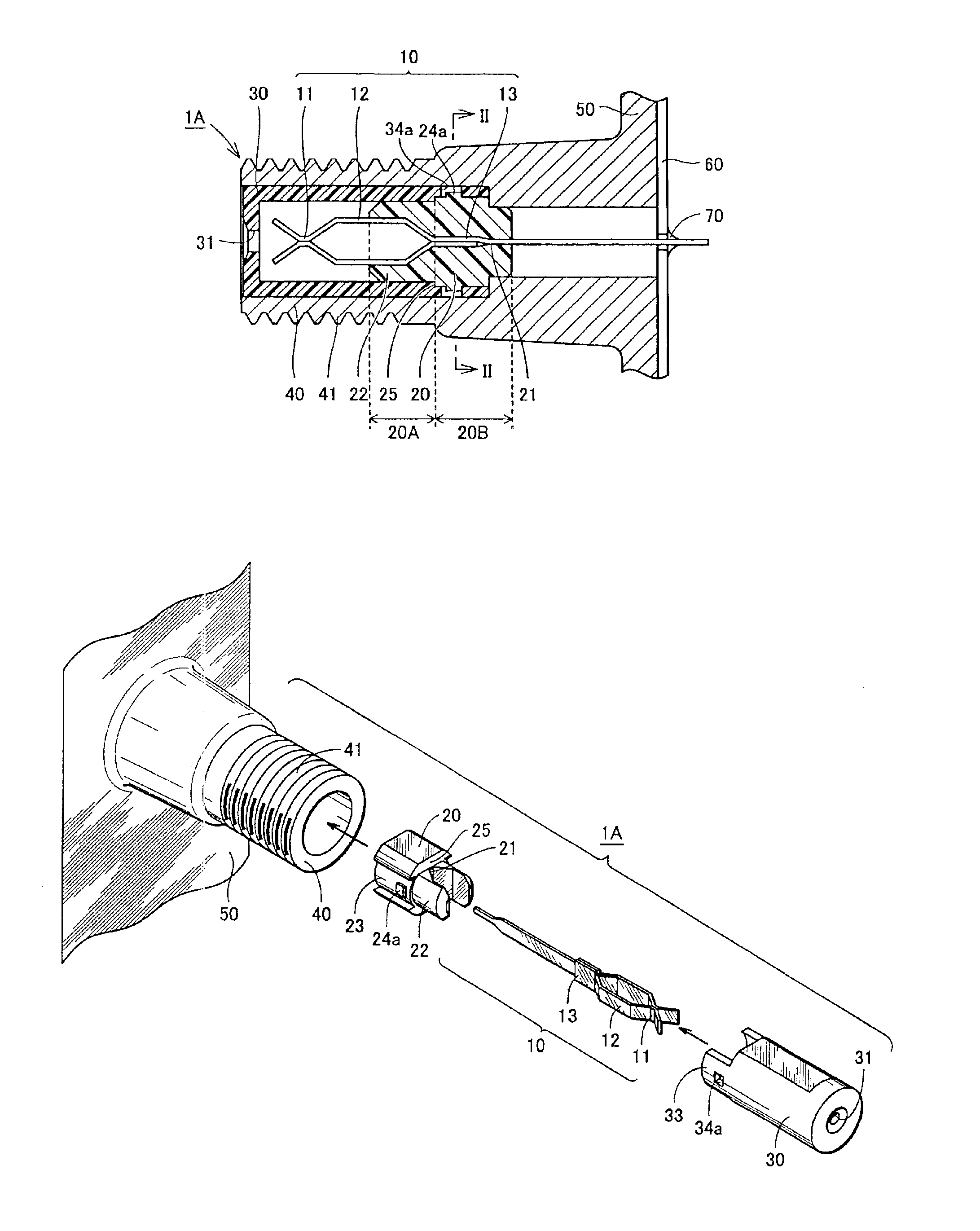
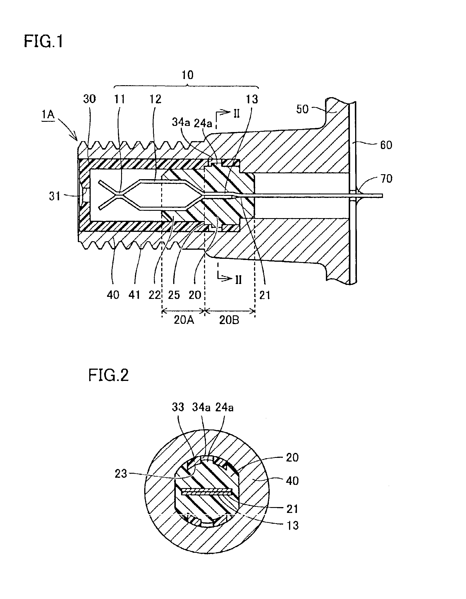
A structure of a coaxial connector according to a first embodiment of the present invention will be described referring to FIGS. 1 to 3. Herein, the same portions as those in conventional coaxial connectors 1E and 1F described above are indicated by the same characters in the drawings, and the descriptions thereof will not be repeated.
As shown in FIG. 1, similar to conventional coaxial connectors 1E and 1F described above, a coaxial connector 1A in this embodiment is formed with central contact 10, first holding member 20, second holding member 30, and shell 40. First holding member 20 has first region 20A holding spaced portion 12 of central contact 10 and second region 20B holding trunk portion 13.
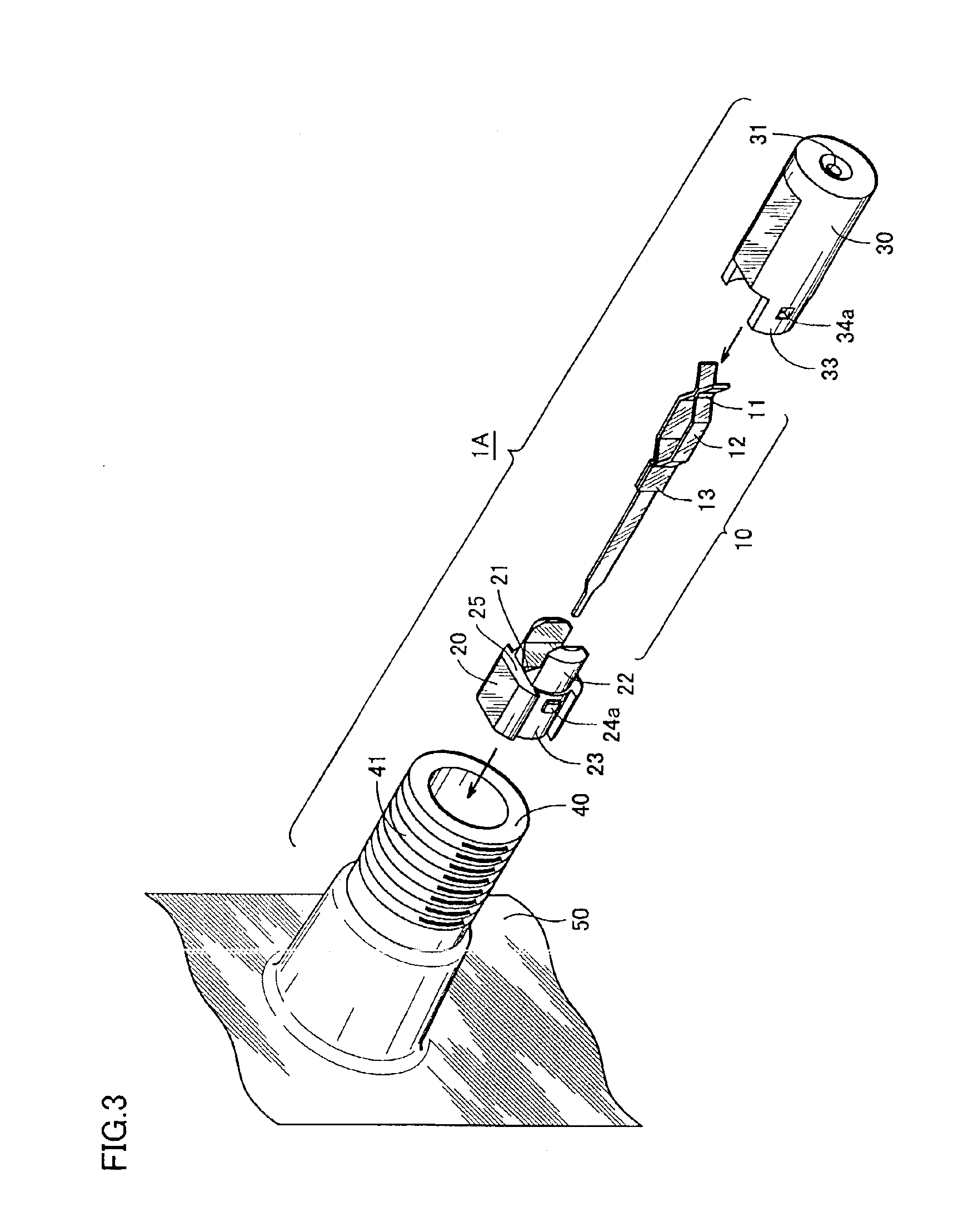
As shown in FIG. 3, similar to conventional coaxial connectors 1E and 1F, coaxial connector 1A in this embodiment is assembled by inserting central contact 10 into square hole 21 of the first holding member, linking second holding member 30 to link projection 22 of firs...
second embodiment
(Second embodiment)
A structure of a coaxial connector according to a second embodiment of the present invention will be described referring to FIGS. 4 and 5. Herein, the same portions as those in the first embodiment described above are indicated by the same characters in the drawings, and the descriptions thereof will not be repeated.
As shown in FIGS. 4 and 5, a coaxial connector 1B in this embodiment differs from coaxial connector 1A in the first embodiment only in a structure of a disengagement-prevention structure securing the linkage of first and second holding members 20 and 30. In coaxial connector 1B in this embodiment, a fit concave portion 24b is provided on slide channel portion 23 of first holding member 20, and a fit convex portion 34b is provided on protruding portion 33 of second holding member 30.
In coaxial connector 1B in this embodiment, protruding portion 33 of second holding member 30 is guided and inserted into slide channel portion 23 of first holding member 20...
third embodiment
(Third Embodiment)
A structure of a coaxial connector according to a third embodiment of the present invention will be described referring to FIGS. 6 and 7. Herein, the same portions as those in the first and second embodiments described above are indicated by the same characters in the drawings, and the descriptions thereof will not be repeated.
As shown in FIGS. 6 and 7, a coaxial connector 1C in this embodiment is not provided with a disengagement-prevention structure to secure the linkage of first and second holding members 20 and 30. In place of the disengagement-prevention structure, a fit pawl portion 34c is provided on the rear end of second holding member 30, and a fit step portion 44c is provided on a prescribed position of an inner surface of shell 40.
By press-fitting first and second holding members 20 and 30 into the cylindrical hole within shell 40 after linking the members, fit pawl portion 34c and fit step portion 44c are fitted, and thus second holding member 30 and s...
PUM
 Abstract
Description
Claims
Application Information
 - Generate Ideas
- Intellectual Property
- Life Sciences
- Materials
- Tech Scout
- Unparalleled Data Quality
- Higher Quality Content
- 60% Fewer Hallucinations
Browse by: Latest US Patents, China's latest patents, Technical Efficacy Thesaurus, Application Domain, Technology Topic, Popular Technical Reports.
© 2025 PatSnap. All rights reserved.Legal|Privacy policy|Modern Slavery Act Transparency Statement|Sitemap|About US| Contact US: help@patsnap.com