
Method of compounding resin and fiber

Inactive Publication Date: 2005-04-05
PLASTICOMP
View PDF29 Cites 25 Cited by
  • Summary
  • Abstract
  • Description
  • Claims
  • Application Information

AI Technical Summary

Benefits of technology

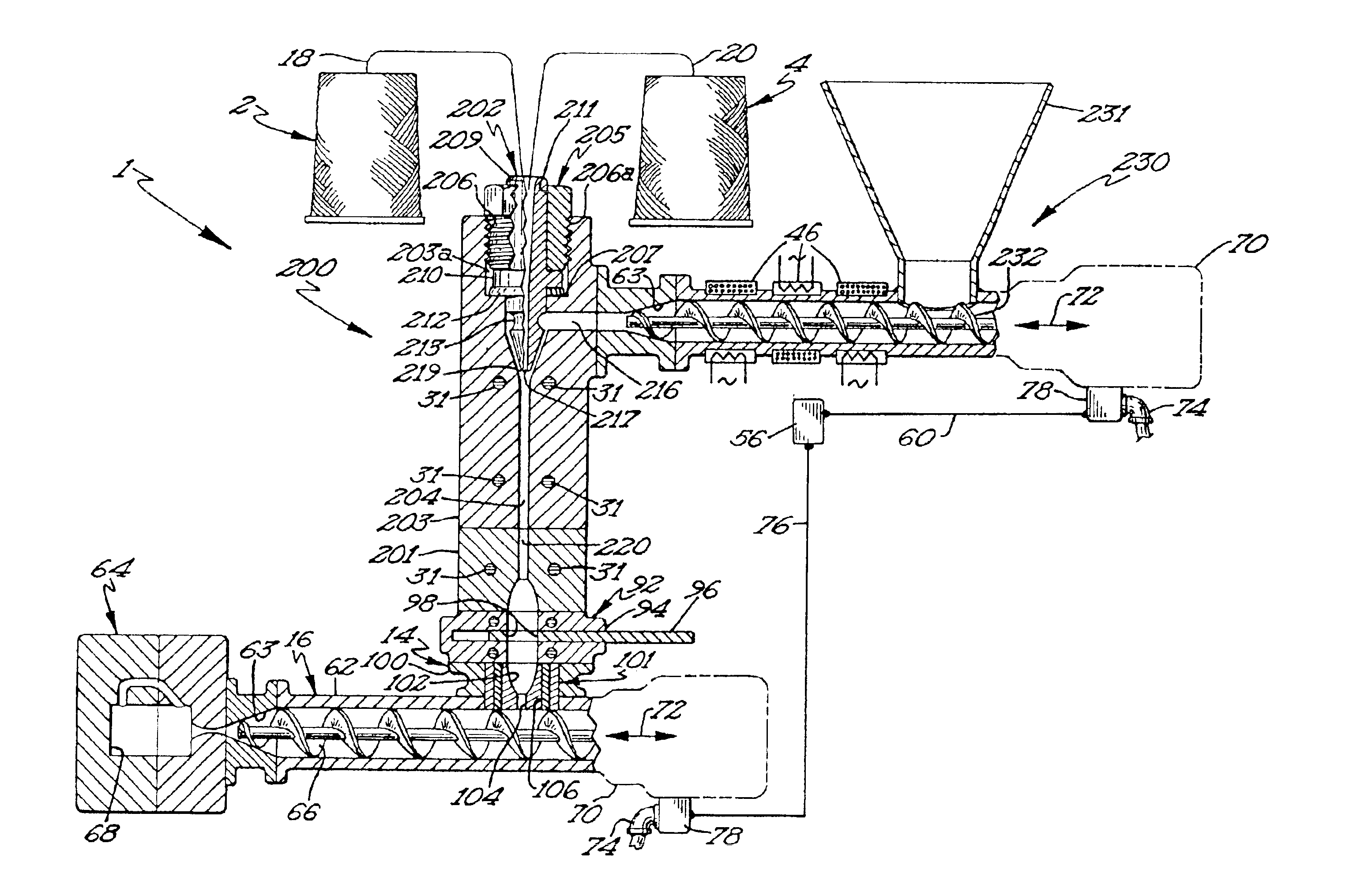
The coating die passage comprises at least one orifice of predetermined size that is larger in cross-sectional area than the cross-sectional area of the fiber strand. The remaining annular space between the fiber strand and the orifice through which molten resin passes defines a predetermined area through which the thermoplastic resin may flow. The ratio of the cross-sectional area of the fiber to the cross-sectional area of the annular space being the means whereby the proportion of resin coating to fiber strand may be controlled.
In another embodiment of the present invention the apparatus for coating and conveying fiber strands with a thermoplastic resin comprises a housing having a fiber inlet and outlet with a fiber entrainment and resin coating passage within the housing connected between the fiber inlet and outlet for the passage of a continuous strand of fiber through the housing. A resin injection port in the housing is in fluid flow communication with the fiber entrainment passage to introduce pressurized resin in a fluid state into contact with the continues strand of fiber in the entrainment passage. A supply of continuous fiber strand is connected to the fiber inlet of the housing and a supply source of molten thermoplastic resin is placed in fluidic communication with the resin injection port in the housing. The pressurized flow of resin into the entrainment passage conveys the continuous strand of fiber through the housing and out of the fiber outlet while coating the fiber with the resin. The resin injection port may be arranged to open upon a resin receiving chamber within the housing having at least one flow passage extending from the resin receiving chamber to the fiber entrainment passage. The resin receiving chamber and the flow passage place the resin injection port in fluidic communication with the fiber entrainment passage. The flow passage extends in the general direction of extent of the fiber entrainment passage and thereby directs pressurized resin in the same general direction as that of fiber movement within the fiber entrainment passage, enhancing the movement of the fiber strand towards the fiber outlet.
One or more back flow chambers may be located upstream from where the injection port communicates with the passage to prevent resin from escaping the coating die through the passage or nozzle.

Problems solved by technology

The loss-in-weight scales necessarily add to the cost and complexity of the compounding apparatus.
None of the known prior art processes for formulating a mixture of fiber reinforced resin for molding purposes are operatively effective for preparing a molding material comprised of fiber reinforced resin for immediate introduction into a molding machine at the same site where the fiber-resin mixture is made.
Nor can any of the known prior art processes for formulating a mixture of fiber reinforced resin for molding purposes operate in a controlled and accurate discontinuous manner.
Either cumbersome and costly apparatus, including multiple stage mixing devices and loss-in-weight scales, are required in the prior processes, and / or the fiber-reinforced resin is extruded into lengths, cut and packaged for sale and transportation to separate molding facilities.

Method used


Image

  • Method of compounding resin and fiber
  • Method of compounding resin and fiber
  • Method of compounding resin and fiber

Examples


Embodiment Construction

Although the disclosure hereof is detailed and exact to enable those skilled in the art to practice the invention, the physical embodiments herein disclosed merely exemplify the invention, which may be embodied in other specific structure. While the preferred embodiment has been described, the details may be changed without departing from the invention, which is defined by the claims.

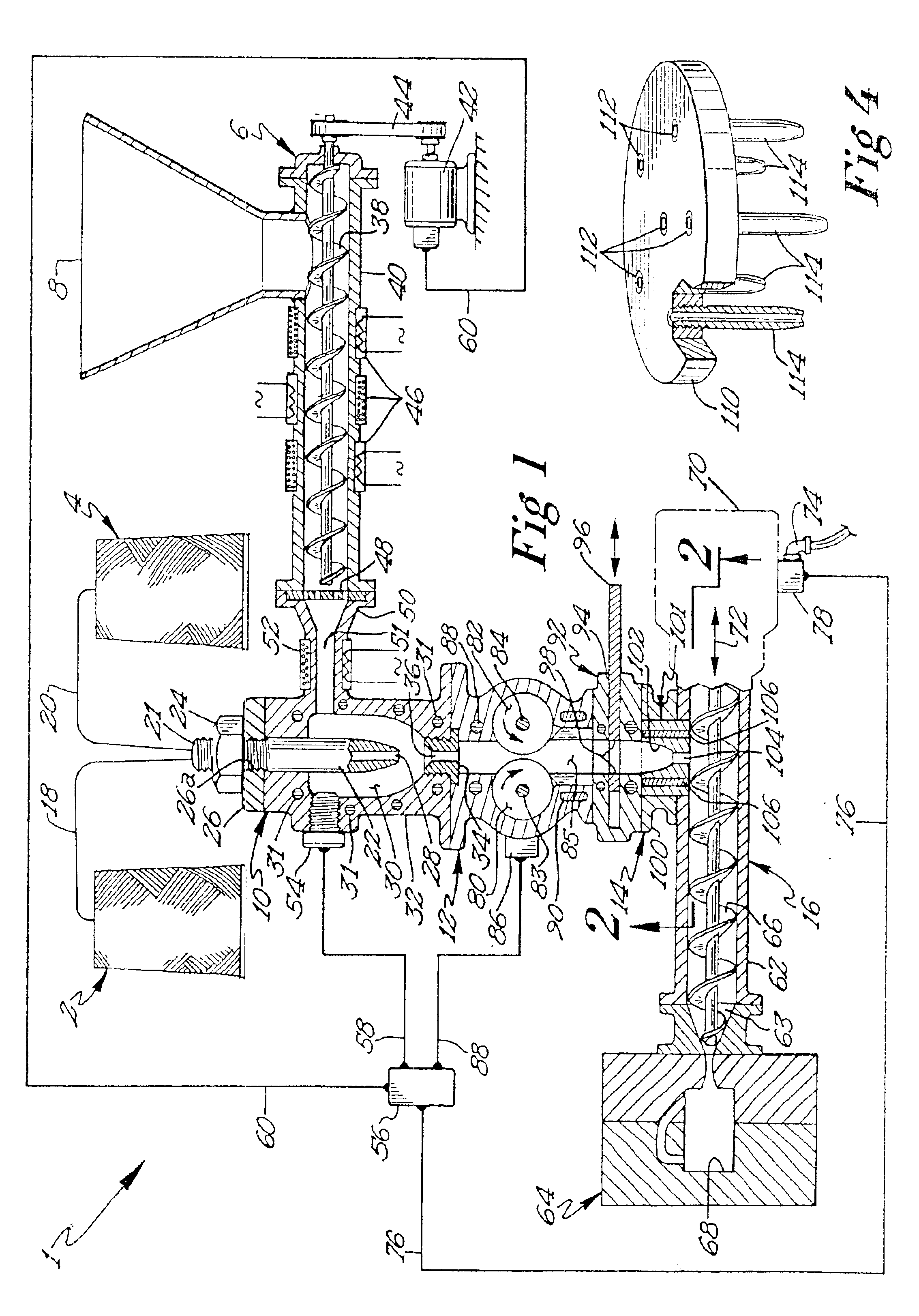
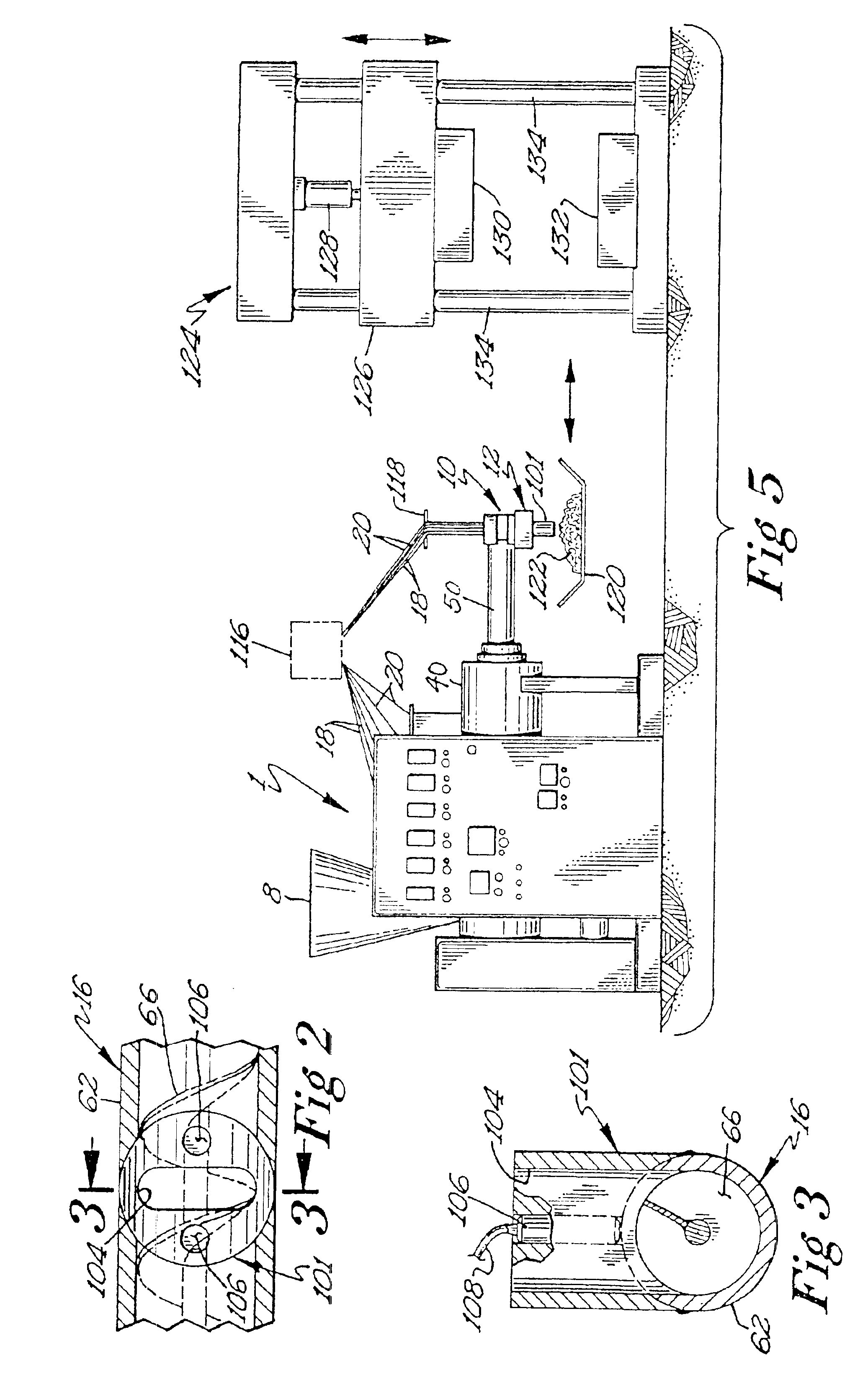
Referring now to the drawings, there is shown in FIG. 1 an embodiment illustrating the apparatus and process of this invention for preparing fiber reinforced resin as a molding charge. The apparatus or system is comprised of spools or rolls of fiber 2, 4, a resin supply extruder 6 having a feed hopper 8, a coating die 10, a fiber and resin conveying device 12, a transition nozzle assembly 14, and a receiving device generally indicated by reference numeral 16. Reinforcing fiber strands, such as glass fiber, is supplied from spools or supply rolls 2 and 4 in the form of strands 18 and 20. Each of the stra...


PUM

PropertyMeasurementUnit
Percent by massaaaaaaaaaa
Pressureaaaaaaaaaa
Pressureaaaaaaaaaa

Abstract

Molding material consisting of resin coated reinforcing fiber strands in a molten mass of resin is prepared at a molding site for controlled supply to a molding machine. Continuous strands of fiber from supply spools are entrained with pressurized, molten resin flowing through a coating device and coated with the resin. The movement of the fiber and resin through the coating die may be controlled so as to accurately and predictably produce any desired quantity the molding material, i.e. the coating apparatus may be operated in a discontinuous manner to provide any predetermined quantity of molding material to a receiving device. The receiving device may be the feed screw for an injection molding machine or simply a plate movable to and from a compression molding machine. The fiber strands may be cut into predetermined lengths by a cutting device positioned downstream of the aforesaid coating device.

Description

FIELD OF USEThis invention relates generally to the field of mixing or compounding reinforcing fiber strands with thermoplastic resin.The fiber strands may be of any predetermined length and are introduced into an admixture with thermoplastic resins for immediate use in molding machines at a product molding facility.BACKGROUND OF THE INVENTIONProcesses are known for combining reinforcing fiber strands with thermoplastic resin to form reinforced plastic composites. U.S. Pat. No. 4,439,387 and Re. 32,772 sharing common inventorship herewith disclose the embedding of thermoplastic resin in reinforcing fiber strands as they are drawn through a forming die having a convoluted passage, in the presence of molten thermoplastic resin introduced from an extruder. The extrusion product of that process comprises an elongated bar or rod having a continuous length of reinforcing fiber encased within thermoplastic resin. That preformed composite may be inserted into a die of an injection molding m...

Claims


Application Information

Patent Timeline
IPC IPC(8): B29B15/10B29B15/12B29C47/00B29C45/18B29C47/50B29C47/10B29C47/38B29C43/00B29C48/06B29C48/38
CPCB29B15/122B29C45/1816B29C47/0004B29C47/0876B29C47/1045B29C47/367B29C47/50B29C47/366B29C47/364B29C47/0064B29C47/0014B29C47/004B29C47/0066B29C2045/466B29K2105/06B29K2105/10B29K2105/12B29C47/1018B29C47/28B29C43/00B29B7/60B29B7/90B29C48/05B29C48/022B29C48/0011B29C48/0021B29C48/0022B29C48/2694B29C48/287B29C48/2886B29C48/34B29C48/37B29C48/385B29C48/387B29C48/38B29C48/40B29C48/06B29B7/905B29B7/38
Inventor HAWLEY, RONALD C.CROSS, PAUL C.HANSEN
Owner PLASTICOMP
Learn More