Longitudinally activated compression sealing device for elongate members and methods for using the same

a longitudinally activated and sealing device technology, applied in the direction of hose connection, cable termination, instrument, etc., can solve the problem that the sealing pressure of the plug would risk damage to the optical fibr

Active Publication Date: 2005-04-05
COMMSCOPE CONNECTIVITY BELGIUM BVBA
View PDF27 Cites 41 Cited by
  • Summary
  • Abstract
  • Description
  • Claims
  • Application Information

AI Technical Summary

Benefits of technology

These aspects of the invention may have the advantage that, because the sealing device comprises sealing elements spaced apart from each other between the compression plates (in order to provide their respective sealing contacts), it may avoid the need to compress a mass of sealing material extending throughout the entire area between the plates as with the above described prior art. This may reduce the compression force required to deform the seals and make the sealing contacts (for a given sealing material). Consequently, it may be easier for the installation engineer to form the seal and for the seal to be formed without damaging the micro-ducts or other elongate articles. Also, the seal may be more reliable because it may be less prone to failure over time due to the use of a lower compression force (in addition to the enhanced reliability due to the seal being easier to form in the first place). Additionally, the use of a lower compression force may mean that the strength and robustness of the various components of the sealing device is generally less critical than hitherto (with the associated manufacturing advantages).
Each sealing element may be a tube. The tube may have a length at least as great as its external diameter. Alternatively, each sealing element may comprise an O-ring, for example. A plurality of O-rings (for example, two) may be located next to each other to form a combined sealing element (and therefore in effect acting as a sealing tube). A possible advantage of a tube-shaped sealing element (or a plurality of O-rings combining to form a single sealing element) is that the sealing contact may be greater than that of a single O-ring, for example. A possible advantage of a tube sealing element over a plurality of O-rings may be that the tube is generally easier to handle and to install.

Problems solved by technology

This use of such plugs runs contrary to the expectation that the plug sealing pressure would risk damaging the optical fibres, such damage not being an issue with electrical cables.

Method used


Image

  • Longitudinally activated compression sealing device for elongate members and methods for using the same
  • Longitudinally activated compression sealing device for elongate members and methods for using the same
  • Longitudinally activated compression sealing device for elongate members and methods for using the same

Examples


Embodiment Construction

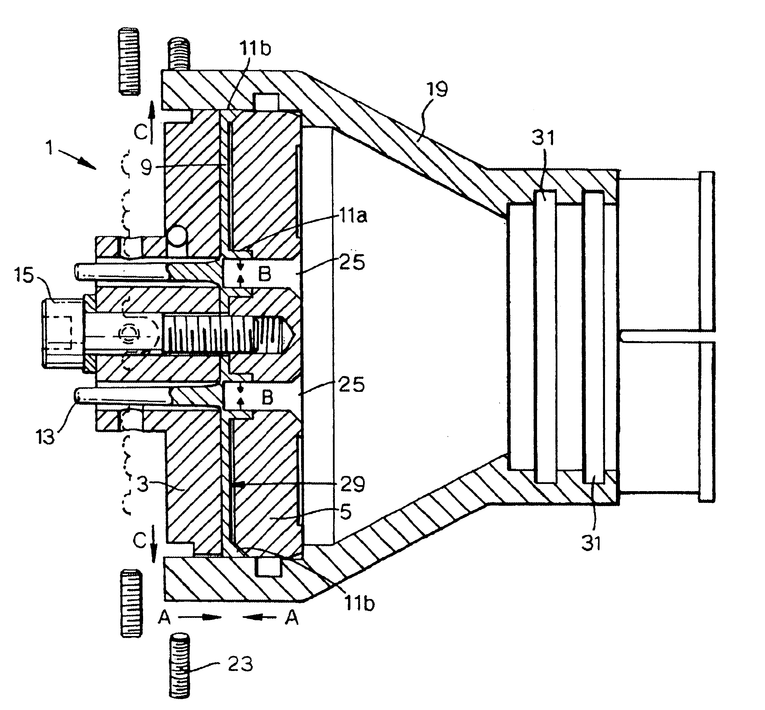
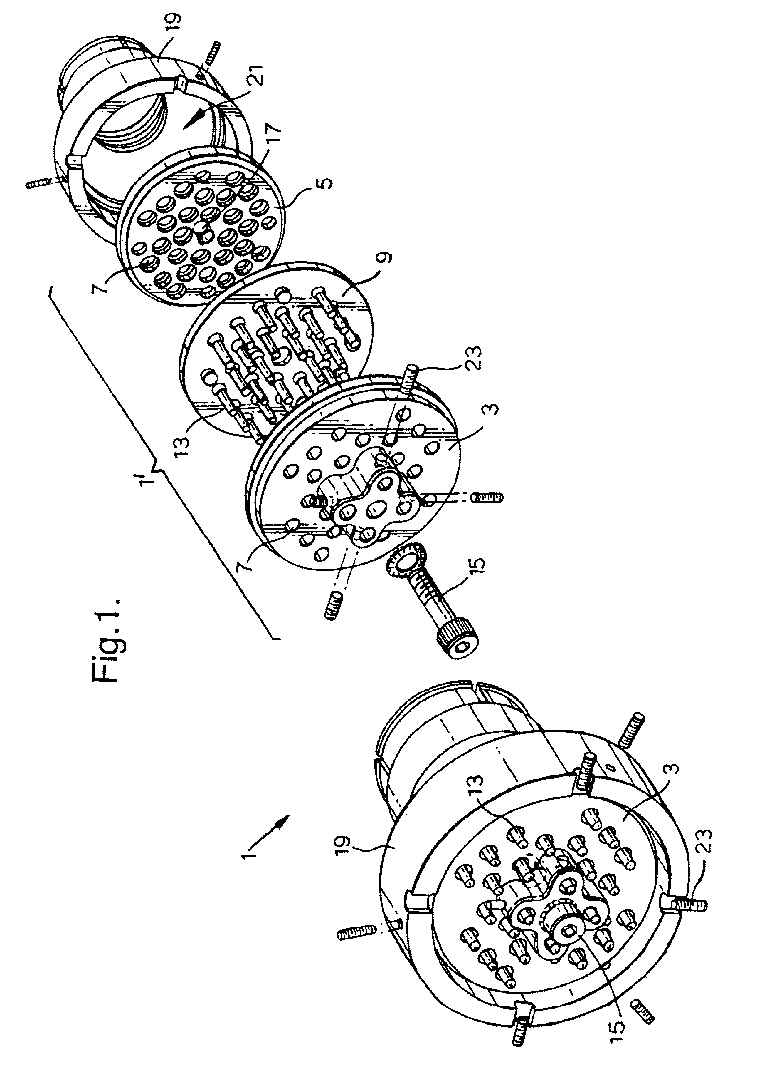
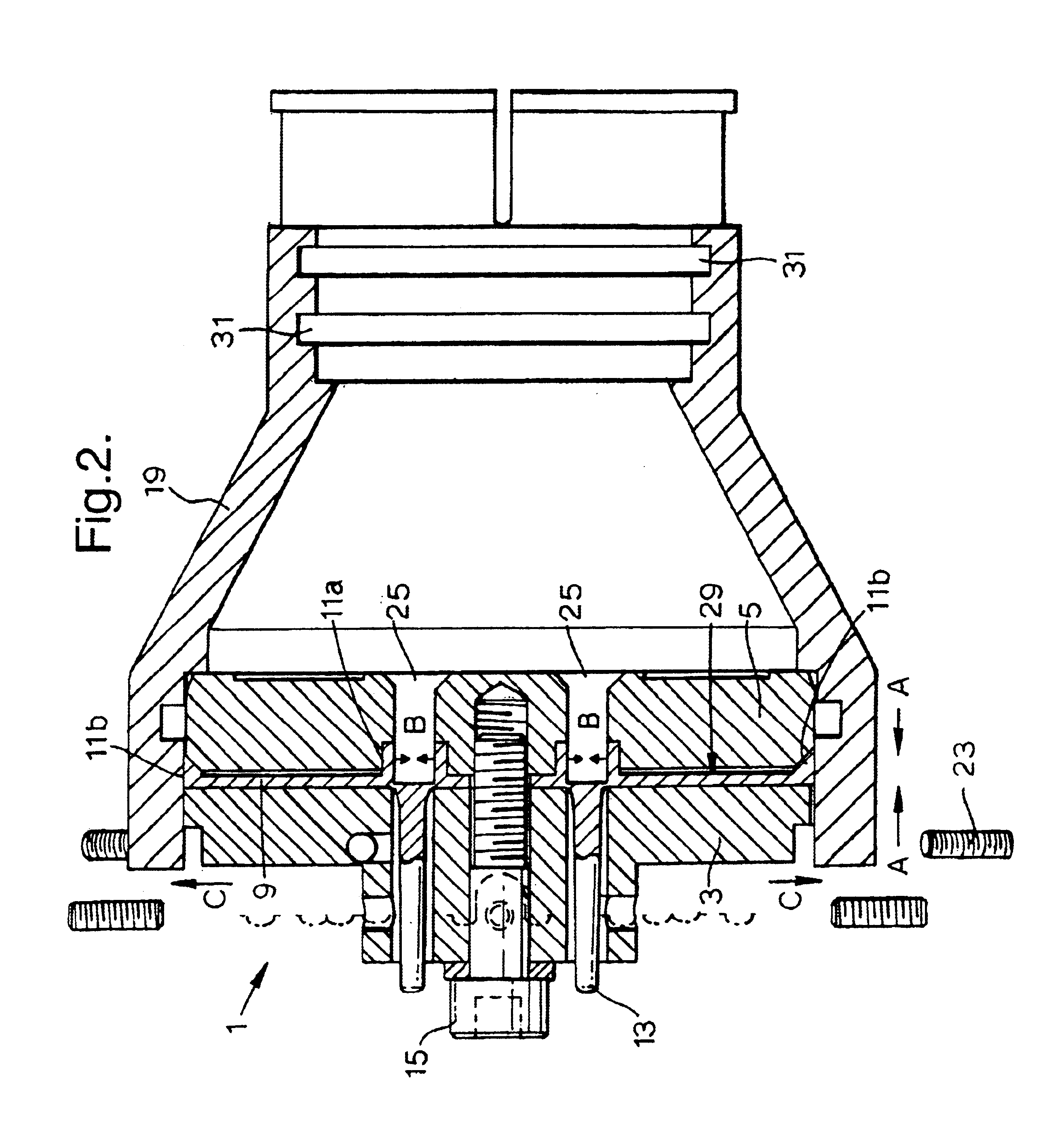
Referring to the drawings, FIG. 1 shows a sealing device 1 including a compression-expandable plug 1′ comprising a pair of compression plates 3 and 5, each of which has a plurality of apertures 7 extending through the plate, through which elongate articles (not shown) may extend during use. Between the compression plates 3 and 5 is a support 9 in the form of a synthetic rubber flexible sheet. The support 9 has attached thereto (and in fact integrally moulded with the sheet) a plurality of second sealing elements 11a in the form of tubes that project from a major surface of the support. Because of the perspective of the drawing, the second sealing elements 11a are not visible in FIG. 1, however, they are shown in cross-section in FIG. 2.

FIG. 1 does, however, show elongate removable blocking parts 13 projecting from the opposite major surface of the support 9 to that from which the sealing element tubes 11 project. Each blocking part 13 is associated with a respective second sealing e...


PUM


Abstract

A compression-expandable plug provides lateral expansion of an elastomeric gasket to seal around mini-tubes within an optical fiber duct, the mini-tubes containing optical fibers. The compression-expandable plug includes an elastomeric gasket having longitudinal passages configured to be positioned around optical-fiber-containing mini-tubes in an optical fiber duct and means for longitudinally compressing the gasket thereby laterally expanding it to exert sealing pressure around the mini-tubes and between the mini-tubes and the duct. A means for limiting the longitudinal compression applied to the gasket to limit the sealing pressure to a level selected to limit damage to the optical fibers may be provided.

Description

RELATED APPLICATIONSThis application claims priority from Great Britain Application No. 0227985.9, filed Nov. 30, 2002 and Great Britain Application No. 0323267.5, filed Oct. 4, 2003, the disclosures of which are hereby incorporated herein by reference.BACKGROUND OF THE INVENTIONThe present invention relates to sealing devices and, more particularly, to sealing devices for sealing an opening in an object between the object and at least one elongate article extending through the opening, for example, sealing the end of a duct through which one or more cables, pipes or smaller ducts (often formed “micro-ducts”) extend.It is known to seal an opening in an object, such as a splice case in which splices between telecommunications or power cables are enclosed. A variety of approaches are known for sealing in such environments. One type of known seal for such enclosures includes the use of a pair of compression plates and a deform able sealing material between the plates that is deformed i...

Claims


Application Information

Patent Timeline
Patent Type & Authority Patents(United States)
IPC IPC(8): G02B6/44H02G15/00H02G15/013
CPCG02B6/4444H02G15/013Y10T24/14G02B6/44775G02B6/4459
Inventor BUEKERS, VALEREBRANTS, JOSALAERTS, ROGERVRANCKX, FONSWILKINSON, RANDYCROCE, JAMES A.CHEN, CHIEN-ANHARDIE, DAVID J.
Owner COMMSCOPE CONNECTIVITY BELGIUM BVBA
Why Eureka
Try Eureka