Auto focus for a flow imaging system

a flow cytometry and autofocus technology, applied in the field of automatic focus of optical systems, can solve the problems of insufficient insufficient detail of information generated by these mature technologies, and inability to accurately determine the spatial resolution of prior art flow cytometry, etc., and achieve the effect of less modulation

Inactive Publication Date: 2005-04-05
CYTEK BIOSCI
View PDF62 Cites 77 Cited by
  • Summary
  • Abstract
  • Description
  • Claims
  • Application Information

AI Technical Summary

Problems solved by technology

However, achieving this improved understanding will likely require the ability to extract a far greater amount of information from cells than can currently be achieved using existing tools.
The information generated by these mature technologies, while useful, is often not as detailed as would be desired.
However, prior art flow cytometry offers little spatial resolution, and no ability to study a cell over time.
A key issue that arises in cell analysis carried out with imaging systems is the measurement of the velocity of a cell or other object through the imaging system.
However, the method is computation intensive, limiting the rate at which the velocity estimate is updated using readily available processors.

Method used


Image

  • Auto focus for a flow imaging system
  • Auto focus for a flow imaging system
  • Auto focus for a flow imaging system

Examples


Embodiment Construction

Overview of the Present Invention

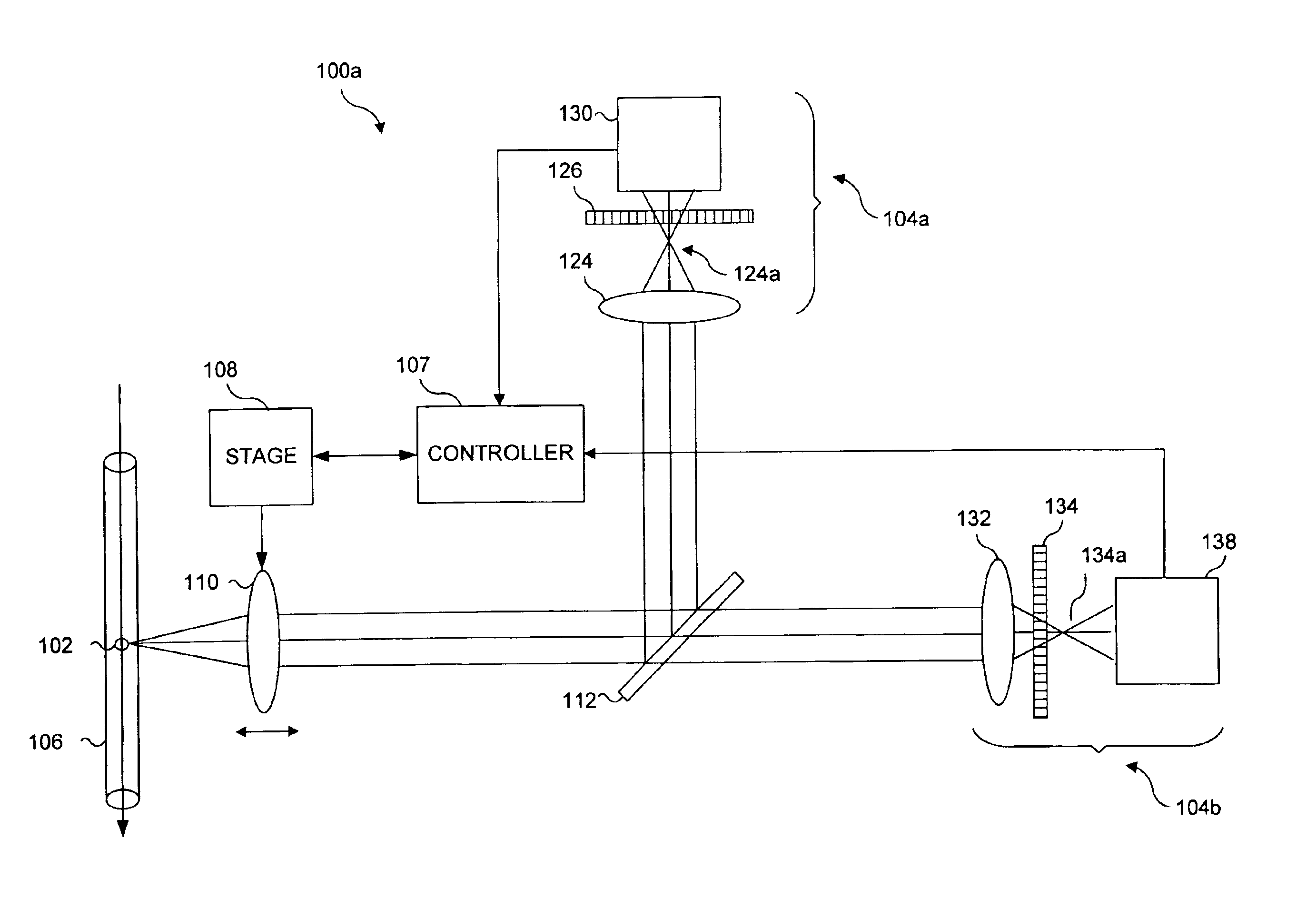
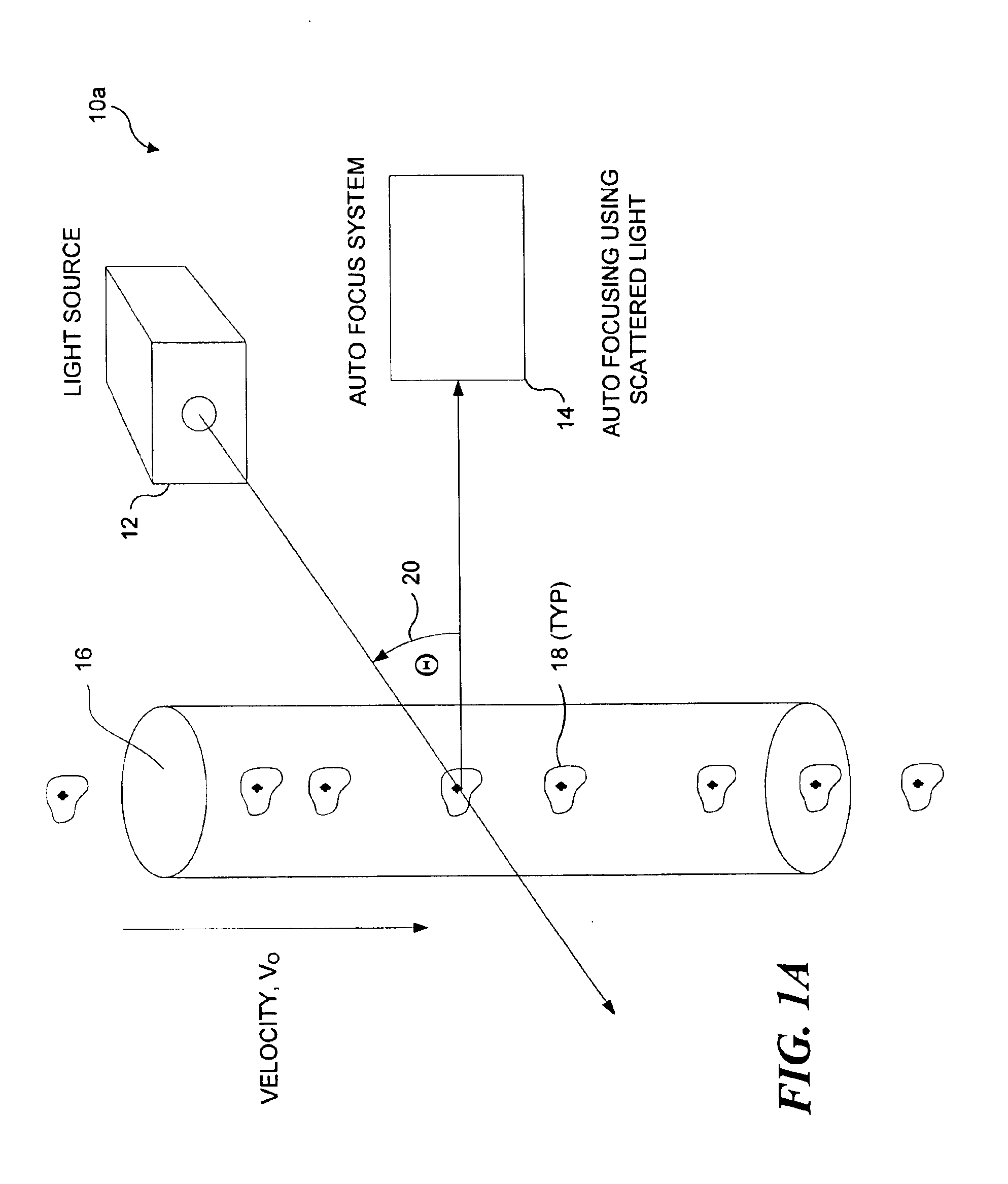
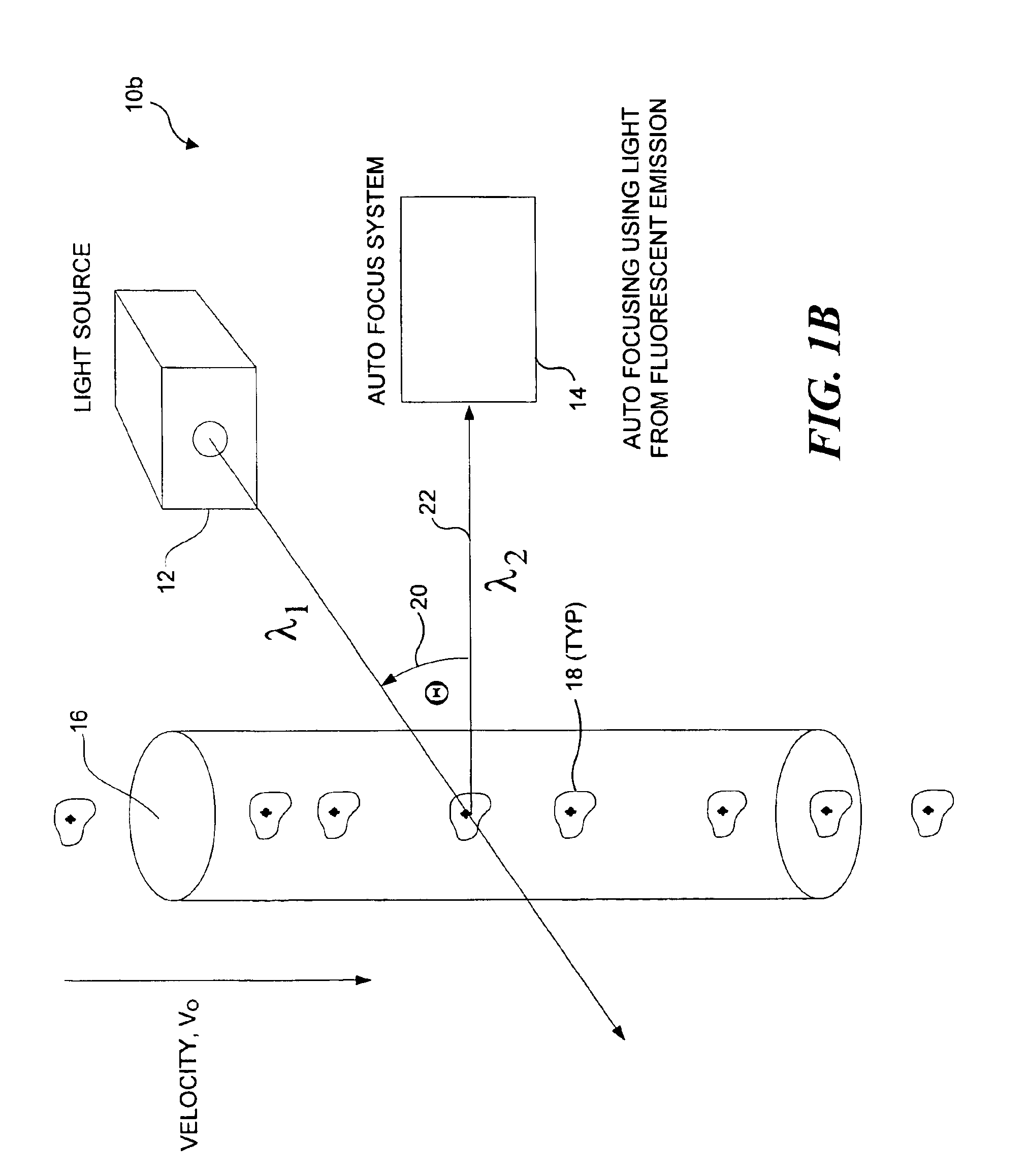
The present invention relates auto focusing systems and methods. Preferably, the present invention is implemented in a flow imaging system. However, the present invention can be used for applications not only where objects are entrained in a flow of fluid passing through an imaging system, but also wherever there is relative movement between objects of interest and the imaging system. In accord with the present invention, auto focusing is achieved by diverting light from an object along two optical legs (or more preferably, two light paths), each of which includes an optical grating that modulates light from the object such that the modulated light has a frequency proportional to the velocity of the object.

Each of the two modulation paths also includes a detector configured to receive the modulated light. The optical gratings are disposed in different positions in each modulation path relative to a point along each modulation path where an image of t...


PUM

PropertyMeasurementUnit
diameteraaaaaaaaaa
diameteraaaaaaaaaa
diameteraaaaaaaaaa

Abstract

A pair of optical gratings are used to modulate light from an object, and the modulated light from either optical is used to determine the velocity of the object. Each optical grating is offset from a reference focal point by the same distance, one grating being offset in a positive direction, the other in a negative direction. Signals produced in response to the modulated light can be processed to determine a direction in which a primary collection lens should be moved in order to improve a focus of the imaging system on the object. The lens is moved incrementally in the direction so determined, and the process is repeated until an optimal focus is achieved. In a preferred embodiment, the signals are weighted, so that the optical grating disposed closest to the optimal focus position contributes the most to velocity detection.

Description

FIELD OF THE INVENTIONThe present invention generally relates to a method and apparatus for automatically focusing an optical system, and more specifically, to a method and apparatus used to enable auto focusing of objects in flow, for a flow imaging system.BACKGROUND OF THE INVENTIONCells and groups of cells are three-dimensional objects containing rich spatial information. Many different analytical probes, which preferentially bind to specific target receptors within a cell, are available to identify the distribution of different bio-molecules within a cell. There is a growing interest in studying cells as dynamic structures including numerous interacting feedback control systems. Understanding cells as dynamic structures, as opposed to static structures, can lead to the development of new drugs, better diagnostic procedures, more effective therapies, and better health care management strategies. However, achieving this improved understanding will likely require the ability to ext...

Claims


Application Information

Patent Timeline
Patent Type & Authority Patents(United States)
IPC IPC(8): G01N15/14G02B27/00G06T7/20G01N15/10
CPCG01N15/1459G06T7/20G02B27/0012G06K9/00134G01N15/1463G01N2015/1018G01N2015/1443G01N2015/1452G01N2015/1497G01N2015/1447G06V20/693
Inventor ORTYN, WILLIAM E.SEO, MICHAEL J.BASIJI, DAVID A.FROST, KEITH L.PERRY, DAVID J.
Owner CYTEK BIOSCI
Why Eureka
Try Eureka