
Organic light-emitting panel and manufacturing method thereof

a light-emitting panel and organic technology, applied in the direction of discharge tube main electrodes, discharge tube luminescnet screens, incadescent cooling arrangements, etc., can solve the problems of reducing the limiting the resolution of the organic light-emitting diodes, and only forming pins on the periphery of the electroconductive glass, etc., to achieve a wide range of radiation areas, increase heat dissipation paths, and enhanced dimensional stability of the rear board

Inactive Publication Date: 2005-04-05
RITDISPLAY
View PDF9 Cites 2 Cited by
  • Summary
  • Abstract
  • Description
  • Claims
  • Application Information

AI Technical Summary

Benefits of technology

Compared to the prior art, owing to the increased heat dissipation paths and enlarged radiation area, heat generated from the front board may be effectively transferred to the rear board and then dissipated. In addition, since the rear board is fitted into the heat spreader with the second surface of the rear board partially exposed, stresses generated during the warpage of the rear board may

Problems solved by technology

In this method, however, pins only can be formed on a periphery of the electroconductive glass.
Thus, the large-scale demands for the organic light-emitting diodes cannot be satisfied, and the resolution of the organic light-emitting diodes is further limited.
Meanwhile, heat generated from the organic light-emitting diodes is almost concentrated on the middle of the device, and the problem of poor heat dissipation paths is also caused.
Although the method may solve the problem of large-scale devices, there are some practical problems to be overcome because the printed circuit

Method used


Image

  • Organic light-emitting panel and manufacturing method thereof
  • Organic light-emitting panel and manufacturing method thereof
  • Organic light-emitting panel and manufacturing method thereof

Examples


Embodiment Construction

The organic light-emitting panel and the manufacturing method thereof in accordance with preferred embodiments of the invention will be described with reference to the accompanying drawings, wherein the same reference numbers denote the same elements.

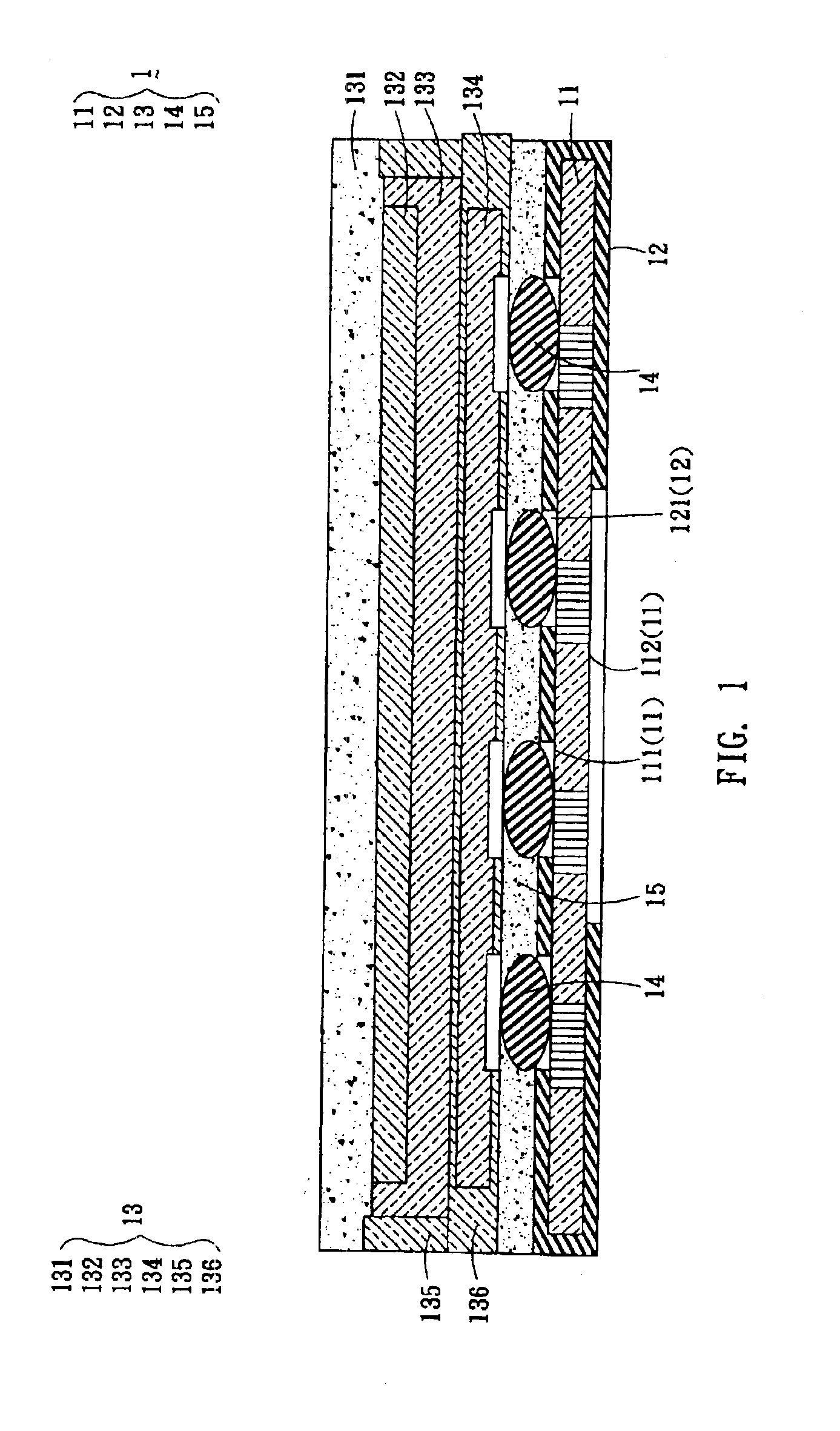
Referring to FIG. 1, an organic light-emitting panel 1 according to one embodiment of the invention includes a rear board 11, a heat spreader 12 and a front board 13. The rear board 11 has a first surface 111 and a second surface 112 opposite to the first surface 111. The heat spreader 12 covers over the first surface 111 of the rear board 11 and extends to the second surface 112 of the rear board 11. The heat spreader 12, which covers over the first surface 111 of the rear board 11 is formed with plural holes 121. The front board 13 is set on the first surface 111 covered by the heat spreader 12.

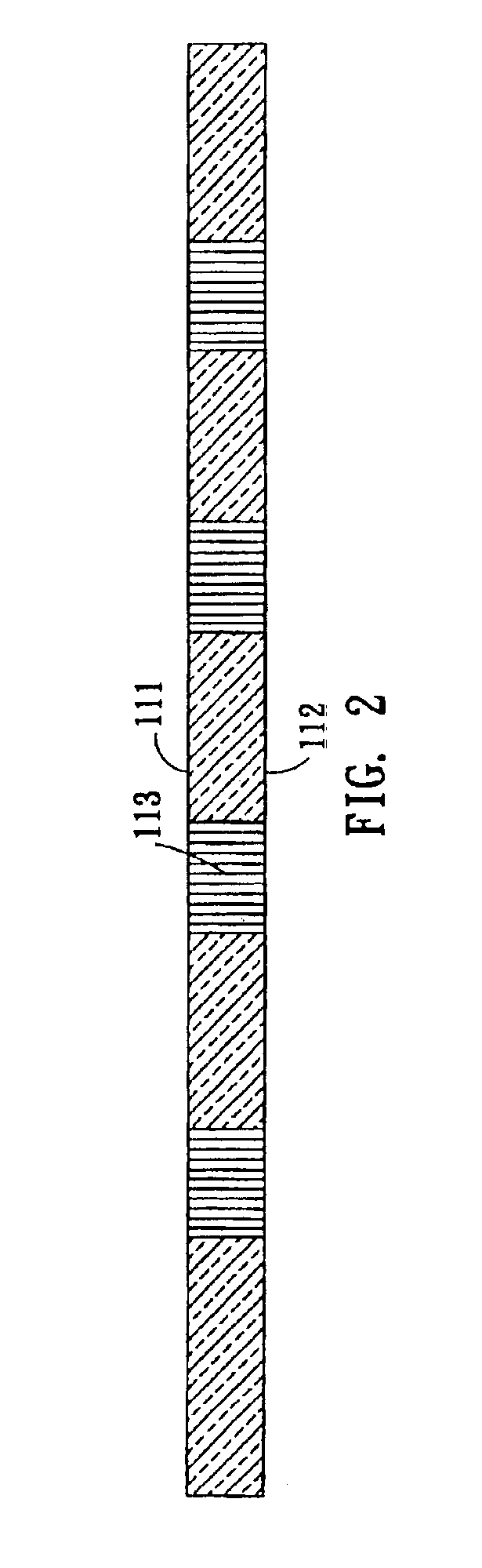
As shown in FIG. 2, the rear board 11 of the embodiment is a printed circuit board (PCB) having internal circuits 113. The printed circuit boa...


PUM


Abstract

An organic light-emitting panel includes a rear board, a heat spreader and a front board. In this case, the rear board has a first surface and a second surface opposite to the first surface. The heat spreader covers over the first surface and extends to the second surface. The heat spreader, which covers over the first surface of the rear board is formed with plural holes. The front board is set on the first surface and the heat spreader. The invention also discloses a manufacturing method of the panel. The method includes the steps of: fitting a rear board into a heat spreader in such a manner that the heat spreader covers over a first surface of the rear board and extends to a second surface opposite to the first surface of the rear board; and adhering a front board to the first surface of the rear board and the heat spreader.

Description

BACKGROUND OF THE INVENTION1. Field of the InventionThe invention relates to an organic light-emitting panel and a manufacturing method thereof and, in particular, to an organic light-emitting panel, in which the heat dissipation paths and area may be improved, and a manufacturing method thereof.2. Description of the Related ArtIn the conventional methods for packaging organic light-emitting diodes, wire layout is made on a surface of the electroconductive glass. In this method, however, pins only can be formed on a periphery of the electroconductive glass. Thus, the large-scale demands for the organic light-emitting diodes cannot be satisfied, and the resolution of the organic light-emitting diodes is further limited. Meanwhile, heat generated from the organic light-emitting diodes is almost concentrated on the middle of the device, and the problem of poor heat dissipation paths is also caused.Another method for packaging organic light-emitting diodes is called as an array area met...

Claims


Application Information

Patent Timeline
IPC IPC(8): H05B33/22H01L51/52
CPCH05B33/22H01L51/529H10K50/87
Inventor WU, CHIN-LONGPAI, SUNG-YIHUANG, TIEN-WANG
Owner RITDISPLAY
Features
  • Generate Ideas
  • Intellectual Property
  • Life Sciences
  • Materials
  • Tech Scout
  • Unparalleled Data Quality
  • Higher Quality Content
  • 60% Fewer Hallucinations
Learn More