Determining a position of objects in a predetermined coordinate system

a technology of predetermined coordinates and objects, applied in the direction of sensors, coils, diagnostics, etc., can solve the problems of reducing the amount of computation associated, affecting the accuracy of measurement results, and long duration, so as to improve the accuracy of measurement results, and improve the effect of accuracy

Inactive Publication Date: 2005-04-05
MEGIN OY
View PDF3 Cites 24 Cited by
  • Summary
  • Abstract
  • Description
  • Claims
  • Application Information

AI Technical Summary

Benefits of technology

The advantage of the present invention over prior art is that by means of the arrangement of the invention, the clarifying of the amplitude distributions of signals sent by a certain set of transmitters and received by a certain set of receivers, with one or more receivers, becomes more precise and effective than before. Likewise, thanks to the invention, the choosing of the signals to be transmitted becomes considerably more free than before, specially in terms of frequency and phase. Thanks to the invention, the signals do not have to be orthogonal with each other.
Further, thanks to the invention it is possible to take into account, e.g. in the MEG measurements, the possible movements of the head during the measurement of the actual useful signal. In addition, the invention allows the elimination of external sources of error in order to improve the accuracy of the measurement results.
Further, the method and device of the invention can be easily modified, and the correction calculation to be implemented in the invention may be implemented at a measuring and calculation step each time most suitable.

Problems solved by technology

One problem with the repetition measurements is their long duration, because of which the head of a testee may move during the measurement.
From this automatically follows that the position of the source of the response generated by the brain changes in relation to the measuring device in the middle of measurement, thereby causing errors to the final analysis.
In the positioning method described, the orthogonalisation of the transmitter signals, however, substantially reduces the amount of computation associated with the positioning, so in an implementation in practice, the transmitter signals are orthogonalised.
The requirement of orthogonality sets requirements to the frequencies to be used as well as to the data collection time, and in addition, the supposition of orthogonality for non-orthogonal signals causes great errors in the computed amplitude coefficients and thereby also in the positioning.
Even at a time interval like this objects may move, which makes the positioning result worse.

Method used


Image

  • Determining a position of objects in a predetermined coordinate system
  • Determining a position of objects in a predetermined coordinate system

Examples


Embodiment Construction

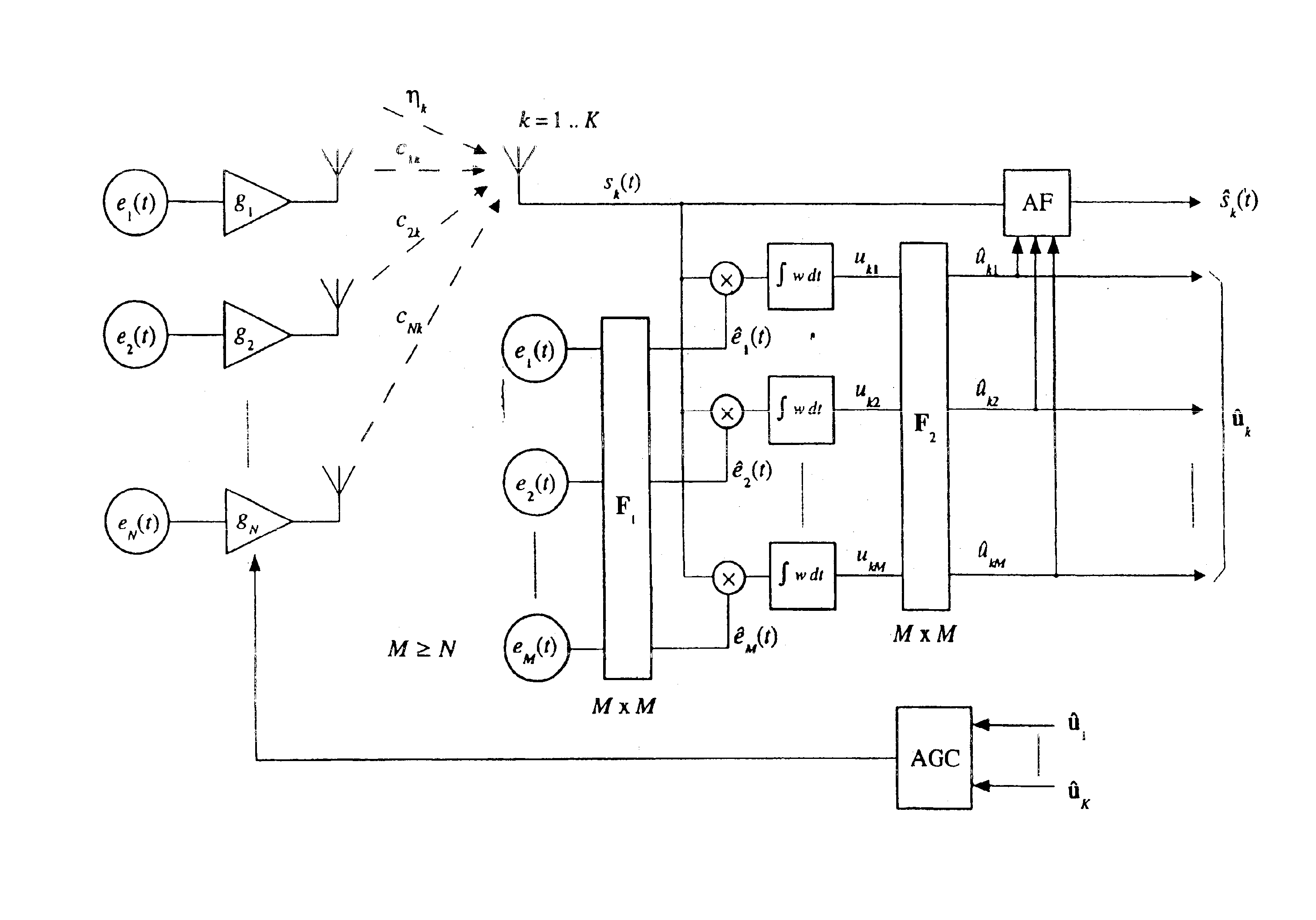
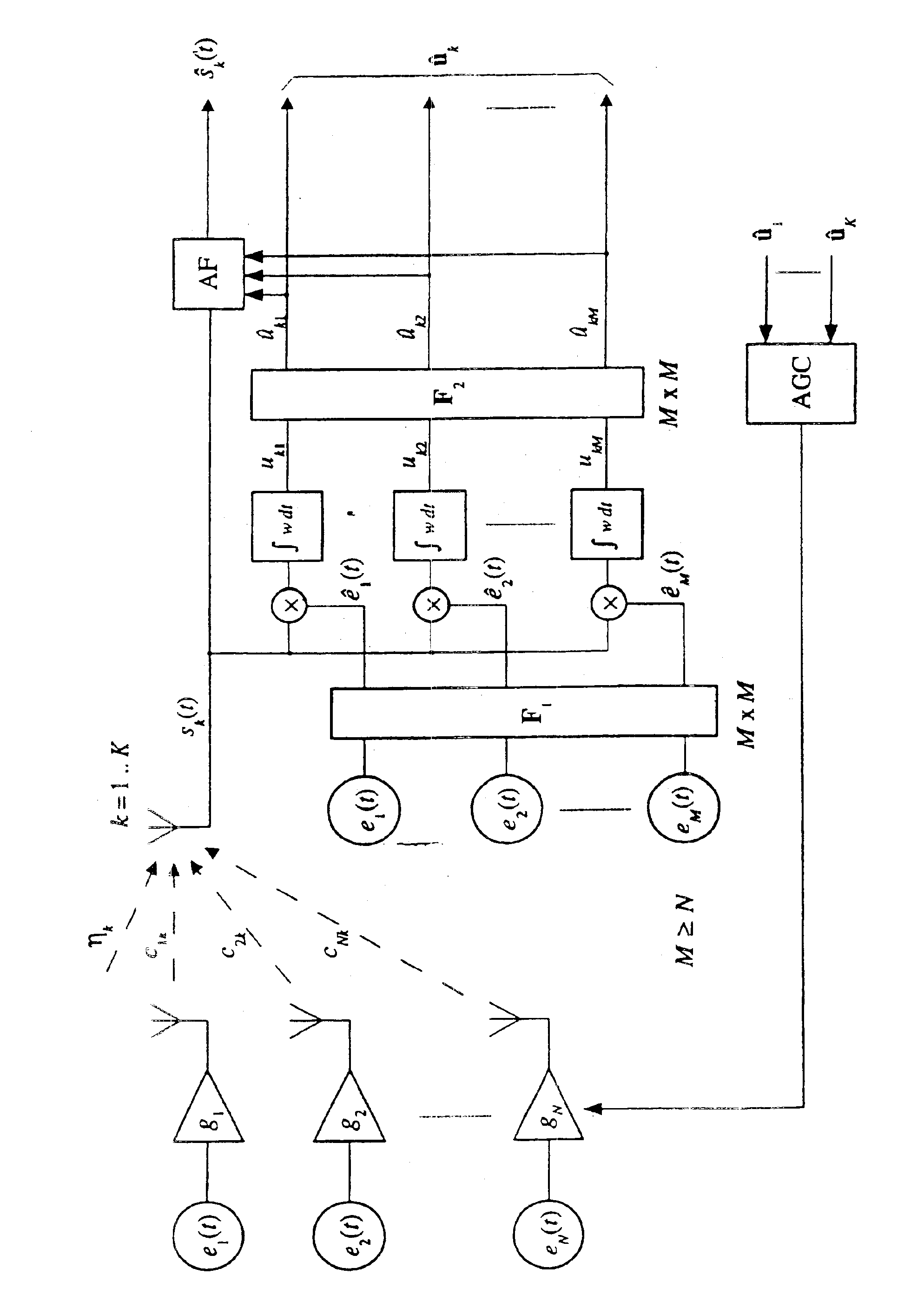
The invention relates to a method which enables one to determine the position and location of an object in relation to another object by means of electromagnetic signals. In the arrangement in accordance with the invention there are two objects, of which to the one there are attached signal sources, i.e. transmitters which generate electromagnetic signals, and the other object contains one or more transmitters for measuring the transmitter signals. Usually the object containing transmitters is the one whose location or position is of interest and which is the object of the measurement. For example, in biomagnetic measurements the object associated with the transmitters is the head of a human being or another restricted part of the body on whose surface the transmitters are placed. By means of the arrangement in accordance with the invention it is possible to find out the location and position of the head, in which case the source areas of the signals generated by the brain may be sh...


PUM


Abstract

The invention relates to a method and device by means of which the location and position of an object may be determined in relation to another object by electromagnetic signals. In the arrangement in accordance with the invention there are two objects to the one of which there are attached signal sources, i.e. transmitters that generate electromagnetic signals, and the other object contains one or more receivers for measuring the transmitter signals. Usually the object containing transmitters is the one whose location or position is of interest and which is the object of the measurement. For example, in MEG measurements the object associated with the transmitters is the head of a human being on whose surface the transmitters are placed. By means of the arrangement in accordance with the invention is possible to find out the location and position of the head, in which case the location of the signals generated by the brain may be found out and utilized when examining the brain activity. The transmitters are also used to measure the signals emanating from the brain.

Description

FIELD OF THE INVENTIONThe present invention relates to the determining of the position of objects. In particular, the present invention relates to a new and improved method of determining the location and position of objects in relation to each other by means of electromagnetic signals.BACKGROUND OF THE INVENTIONThe location method based on electromagnetic signals has been described, in a very general way independent of the subject of application, e.g. in patent publications U.S. Pat. Nos. 5,747,996, 4,346,384 and DE3326476. In one embodiment, the device comprises a set of signal sources, a set of receivers and one or more signal generators which are used to generate a set of transmitter signals known as concerns their tense to be transmitted by signal sources. In addition, the aforementioned patent publications disclose an analysis method for processing the output signals of the receivers and for using them in calculating the position of an object in relation to another object. Com...

Claims


Application Information

Patent Timeline
Patent Type & Authority Patents(United States)
IPC IPC(8): G01B7/004G01S5/02A61B5/04G01R33/035A61B5/05
CPCG01S5/0247G01B7/004A61B5/04009A61B5/1113A61B5/246
Inventor TAULU, SAMUPARKKONEN, LAURIKAJOLA, MATTI
Owner MEGIN OY
Why Eureka
Try Eureka