Holographic interferometry for non-destructive testing of power sources

a technology of power source and interferometer, which is applied in the field of electrical engineering, can solve the problems of affecting the properties of assembled devices, affecting the service life of defective devices, and affecting the service life of such devices, so as to achieve the effect of assessing the homogeneity of electrodes, and ensuring the accuracy of measurement results

Inactive Publication Date: 2011-03-22
ENERIZE CORP
View PDF10 Cites 2 Cited by
  • Summary
  • Abstract
  • Description
  • Claims
  • Application Information

AI Technical Summary

Benefits of technology

[0010]The method has several advantages, one of these being that it can determine the response of a device to the kinds of changes in environmental or operating conditions that can indicate flaws or defects that may not be apparent in more standardized tests. For example, and as described below as an advantage of the present invention, the method of holographic interferometry can precisely determine the physical response of battery electrodes to small temperature changes. Such a response can indicate whether the battery electrode is properly formed and installed into the battery.
[0011]The non-destructive method of holographic interferometry as described below is a precise and effective method and tool for automated non-contact quality control.
[0012]Holographic Interferometer is designed for determination of through and non-through the-thickness cracks and foreign inclusions, heterogeneousness of mechanical characteristics and the thickness irregularity of electrode plates and solid electrolytes of the thermal batteries by holographic interferometry method.
[0013]One objective of the present invention is to evaluate the homogeneity and isotropy for thin ring-shaped electrodes and associated solid electrolyte. Holographic interferometry with local thermal loading of the sample was developed to assess electrode homogeneity and quality.
[0014]The purpose is to investigate the effectiveness of various types of thermal loading of electrodes in the process of holographic flaw detection.
[0016]1. To determine a suitable source for the thermal loading of electrodes,

Problems solved by technology

In multi-component structures such as those that comprise energy generation and storage devices such as batteries, supercapacitors, fuel cells, solar cells, and the like, components with defects or abnormal features or flaws can adversely affect the properties of the assembled device.
As a result, the performance and service life of such devices can be significantly reduced (for example, by degraded capacity).
Such defective devices often fail prematurely.

Method used


Image

  • Holographic interferometry for non-destructive testing of power sources
  • Holographic interferometry for non-destructive testing of power sources
  • Holographic interferometry for non-destructive testing of power sources

Examples


example 1

[0081]A thermal battery electrode was evaluated using holographic interferometry. A test article sample was placed in a transparent container which was filled with argon. Then the sample was exposed to local heating by 1 to 2 degrees near the inner opening. Under the influence of thermal loading there occurred temperature-induced deformations of the sample.

[0082]To control for effects of experiment conditions on test results, the container with the electrode was continuously rotated in the plane normal (90 degrees) to the installation axis, its interference portrait being registered at each revolution.

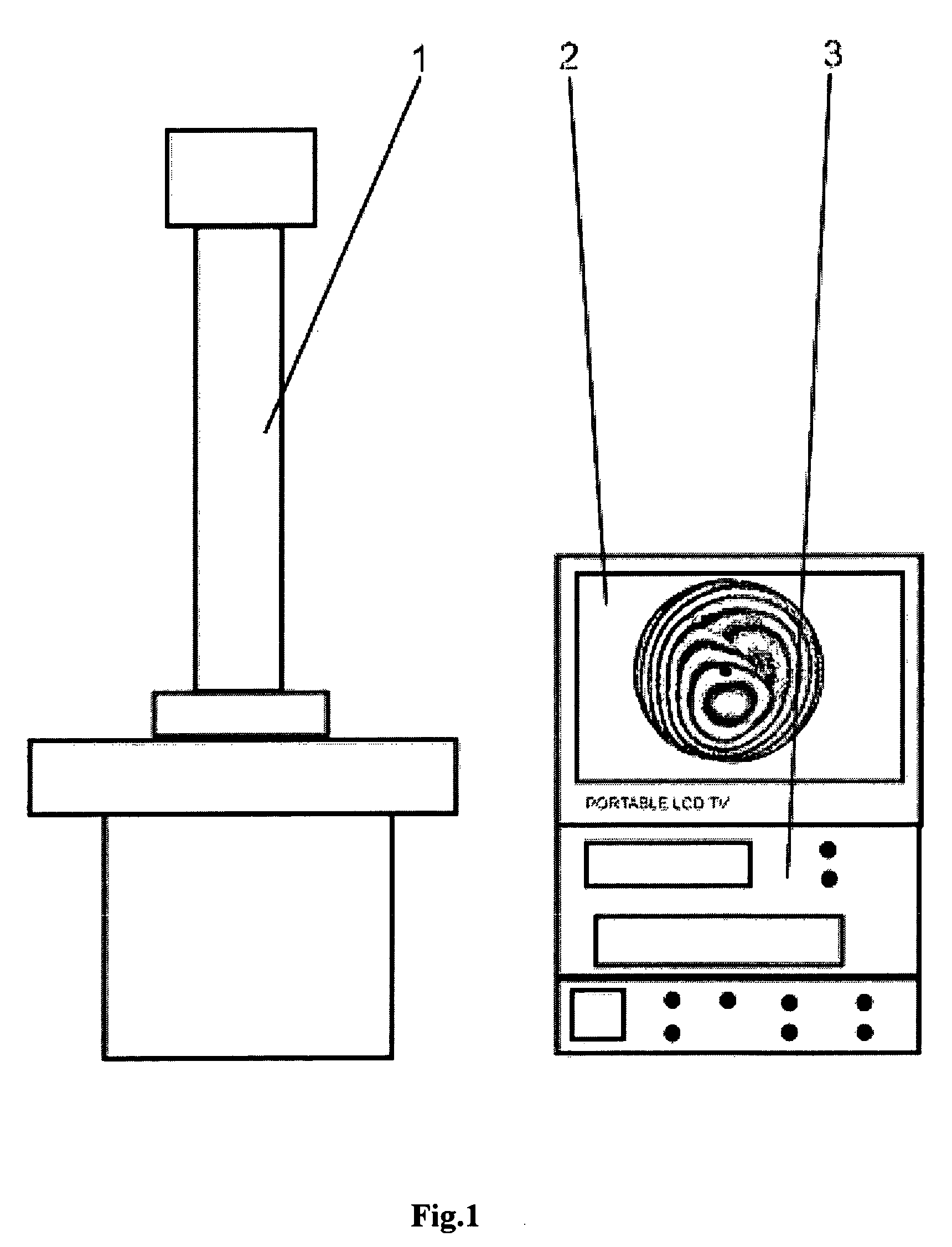
[0083]The interference line images or “portraits” obtained are shown in FIG. 1 (a-r) and FIG. 2 (a-r). These portraits show local heterogeneities along the radial axis. The arrows show distortion zones of interference bands that indicate locations of electrode defects. In the center, the three yellow segments of straight lines show the position of the elements used for heating of the e...

example 2

[0085]Electrode 3 was evaluated using holographic interferometry according to the conditions described on Example 1. The interference line images or “portraits” obtained are shown in FIG. 2 (a-r). These portraits show local heterogeneities along the radial axis. The arrows show distortion zones of interference bands that indicate locations of defects in the electrode. In the center, three yellow segments of straight lines show spirals for heating of electrodes.

[0086]The location of heterogeneities in relation to optical installation scheme changes with rotation. This fact confirms presence of, and points at the location of, heterogeneities in the electrodes being studied.

example 3

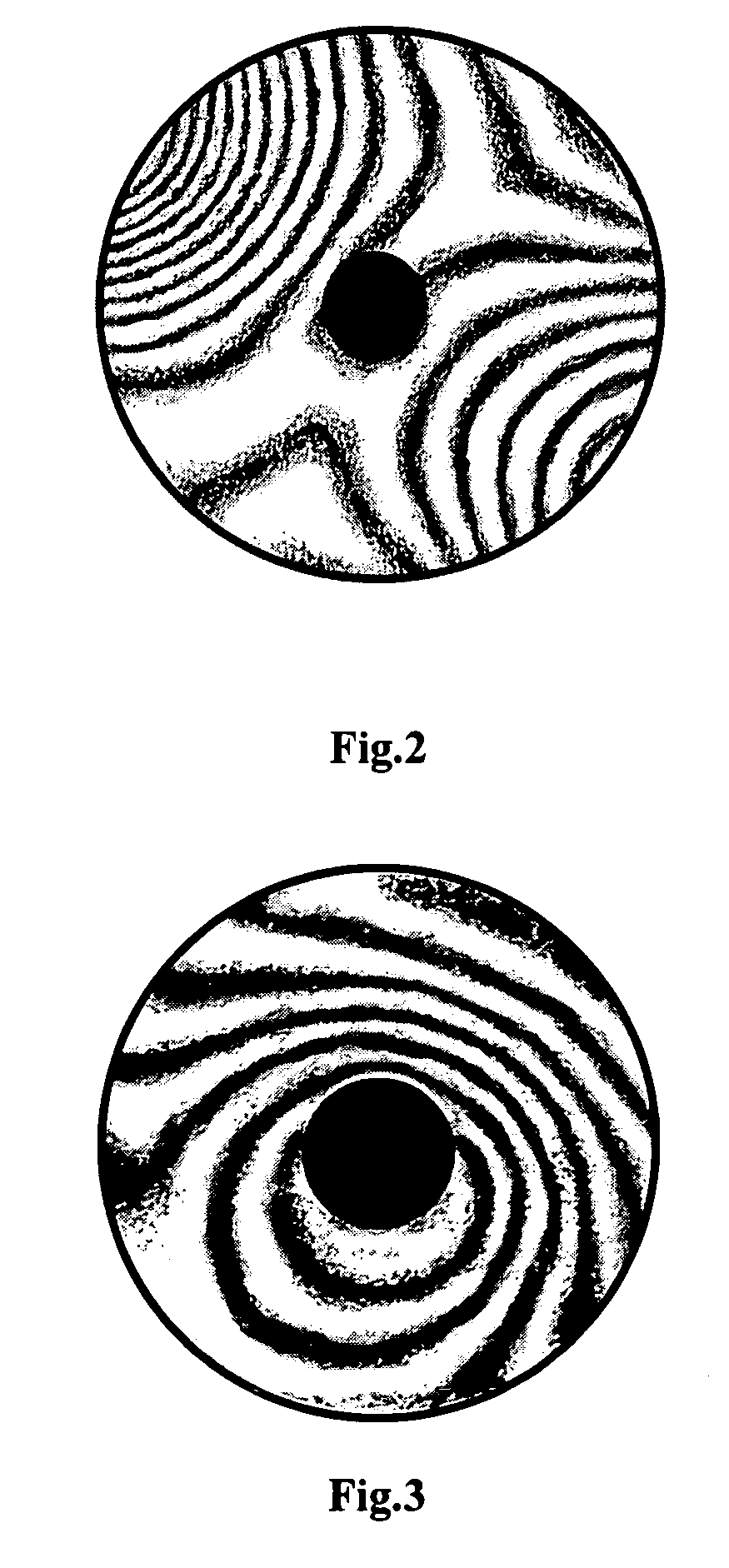
[0087]To control the test the method used, a stainless steel plate that had geometric dimensions similar to those of the electrodes was made and tested. The result is presented on FIG. 3.

[0088]As shown in FIG. 3, the type of the interference bands displays gradually changing curvature that did not depend on the position of the plate in relation with the optical installation scheme. This is evidence of both the heterogeneity and isotropic properties of the test a stainless steel plate. It appears that the axially symmetric thermal loading of an object is the most effective for holographic flaw detection in circular-shape electrodes.


PUM


Abstract

The present invention is connected with the holographic interferometry method and device that provides, to a very high precision, the reconstructing the original waveform of light emitted or reflected by an object. This method allows image resolution close to that of the wavelength of the light being used. The non-destructive method of holographic interferometry coupled with impulse heating of the test article to allow observation of its dynamic response to operating conditions, as described herein, is one of the most effective non-contact automated quality control methods available.

Description

CROSS-REFERENCE TO RELATED APPLICATIONS[0001]Claims priority of Provisional Patent Application No. 60 / 930,601.[0002]Filed May 17, 2007FEDERALLY SPONSORED RESEARCH[0003]NoneSEQUENCE LISTING[0004]NoneFIELD OF THE INVENTION[0005]The present invention relates to electrical engineering, and in particular to the field of physical non-destructive, testing of energy generating and storage device components during and after manufacture, and can be used to determine defects in batteries, supercapacitors, solar cells and fuel cells, and especially in thermal batteries and solid oxide fuel cells.BACKGROUND OF THE INVENTION[0006]In multi-component structures such as those that comprise energy generation and storage devices such as batteries, supercapacitors, fuel cells, solar cells, and the like, components with defects or abnormal features or flaws can adversely affect the properties of the assembled device. As a result, the performance and service life of such devices can be significantly redu...

Claims


Application Information

Patent Timeline
Patent Type & Authority Patents(United States)
IPC IPC(8): G01B9/021
CPCG01B9/021
Inventor REDKO, VOLODYMYRSHEMBEL, ELENA M.SOKHACH, YURII V.KUDREVATYKH, OLEXANDR
Owner ENERIZE CORP
Why Eureka
Try Eureka