Printed circuit board test fixture that supports a PCB to be tested

a technology of printed circuit boards and test fixtures, which is applied in the field of printed circuit boards, can solve the problems of mounting plates and pcbs being tipped, destroying electrical continuity, and growing functionality of these devices, and achieve the effect of preventing tipped

Inactive Publication Date: 2005-04-05
SEAGATE TECH LLC
View PDF24 Cites 23 Cited by
  • Summary
  • Abstract
  • Description
  • Claims
  • Application Information

AI Technical Summary

Benefits of technology

A test fixture for supporting a printed circuit board while it is undergoing electrical testing is provided. The printed circuit board test fixture includes a substantially planar mounting plate which supports a printed circuit board to be tested. A probe support plate holder, positioned above the mounting plate, mechanically couples to a probe support plate and holds the probe support plate opposite, and substantially parallel to, the mounting plate. A base plate is positioned below, and substantially parallel to, the mounting plate. At least three alignment sliders are included, with each alignment slider of the at least three alignment sliders including a guide rail and a runner block slidably coupled to the guide rail. The guide rail of each of the at least three alignment sliders is coupled to, and extends in an upward direction from, the base plate. The runner block of each of the at least three alignment sliders is coupled to the mounting plate to thereby allow for movement of the mounting plate only along an axis perpendicular to a plane of the mounting plate. The mounting pate is also prevented from tilting when test points on the printed circuit board are urged against test probes on the probe support plate. Multiple balancing sliders coupled to the base plate and positioned at a back end of the printed circuit board test fixture.

Problems solved by technology

In electronic equipment such as disc drive data storage systems, the demand for additional power, in both the speed at which they process data and the amount of data they can process, has resulted in a growth in the functionality and an increase in the complexity of these devices.
When relatively large PCBs are mounted and tested on PCB test fixtures that include such centrally supported mounting plates, forces applied near the edges and corners of the PCB when test probes are urged against test points on the PCB can cause the mounting plate and the PCB to tilt.
Such tilting can result in loss of electrical contact between one or more test probes and the PCB test points to thereby destroy electrical continuity and thus provide incorrect test results.

Method used


Image

  • Printed circuit board test fixture that supports a PCB to be tested
  • Printed circuit board test fixture that supports a PCB to be tested
  • Printed circuit board test fixture that supports a PCB to be tested

Examples


Embodiment Construction

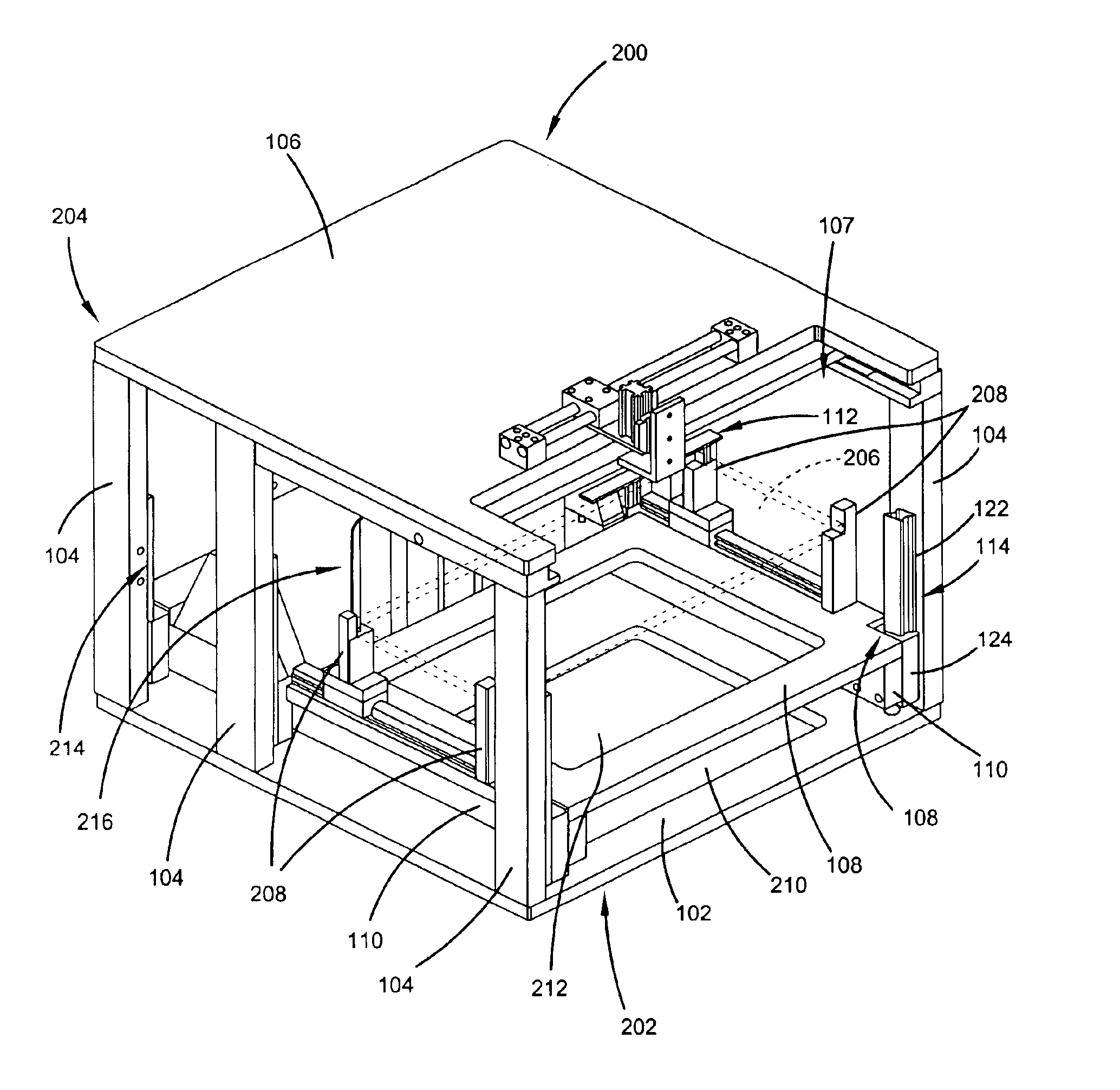
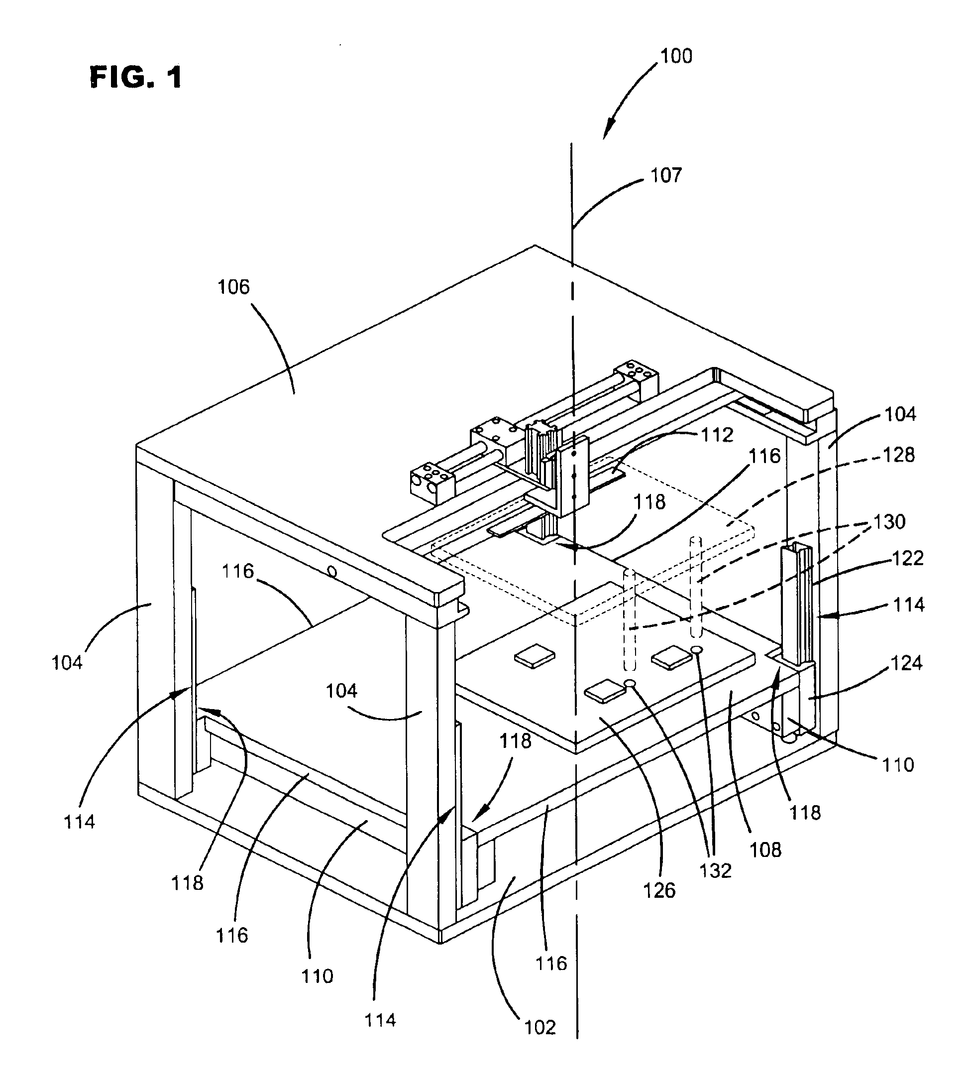
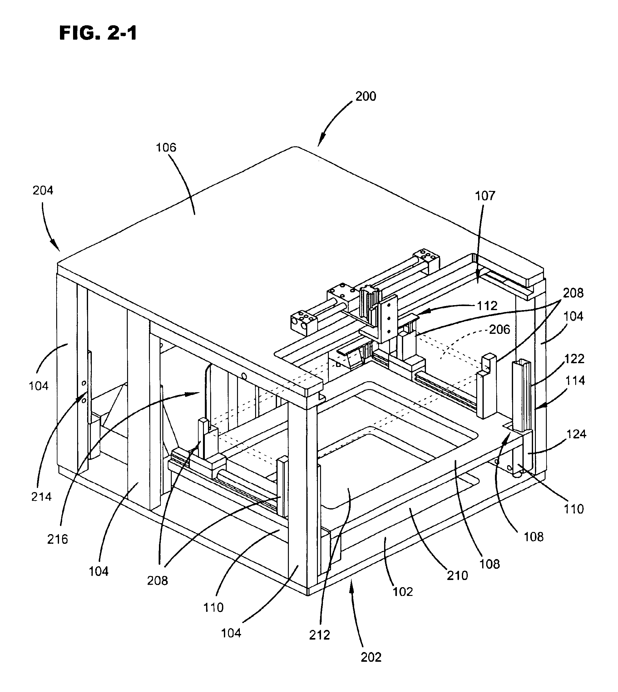
Referring now to FIG. 1, a perspective view of a printed circuit board test fixture 100 in accordance with an embodiment of the present invention is shown. Printed circuit board test fixture 100 includes a base plate 102, support bars 104, a top plate 106, a mounting plate 108, support arms 110, a probe support plate holder 112 and alignment sliders 114.

As can be seen in the FIG. 1, top plate 106 is mounted on support bars 104 that extend in an upward direction from corners of base plate 102. Mounting plate 108, which is substantially planar, is positioned between base plate 102 and top plate 106 and is substantially parallel to base plate 102 and top plate 106. Mounting plate 108 has sides 116 that define corners 118. Each corner 118 of mounting plate 108 is coupled to an alignment slider 114 either directly or via support arm 110. Support arms 110 are substantially parallel to each other and are positioned below, and in contact with, mounting plate 108. Ends of support arms 110 ar...


PUM


Abstract

A printed circuit board test fixture that includes a mounting plate which supports a printed circuit board to be tested is provided. A probe support plate holder, positioned above the mounting plate, mechanically couples to a probe support plate and holds the probe support plate opposite the mounting plate. A base plate is positioned below the mounting plate. At least three alignment sliders are included, with each alignment slider including a guide rail and a runner block slidably coupled to the guide rail. The guide rails are coupled to the base plate. The runner blocks are coupled to the mounting plate to thereby allow for movement of the mounting plate only along an axis perpendicular to a plane of the mounting plate. Multiple balancing sliders coupled to the base plate and positioned at a back end of the printed circuit board test fixture.

Description

FIELD OF THE INVENTIONThe present invention relates generally to printed circuit boards used in electronic equipment such as disc drive data storage systems. In particular, the present invention relates to a test fixture used to support a printed circuit board while it is undergoing electrical testing.BACKGROUND OF THE INVENTIONIn electronic equipment such as disc drive data storage systems, the demand for additional power, in both the speed at which they process data and the amount of data they can process, has resulted in a growth in the functionality and an increase in the complexity of these devices. Printed circuit boards (PCBs) or printed circuit board assemblies (PCBAs) employed in such complex electronic devices include several electrical components, such as integrated circuit chips, that manage the operations of these devices. Several areas on a PCB, such as areas that surround integrated circuit chips, include a large number of closely spaced electrical points or nodes tha...

Claims


Application Information

Patent Timeline
Patent Type & Authority Patents(United States)
IPC IPC(8): G01R31/28
CPCG01R31/2808
Inventor CHUNG, SEE FOOKKUAH, BENG KIATLAU, KUEI PING LINDATAN, THONG CHYE
Owner SEAGATE TECH LLC
Why Eureka
Try Eureka