
Method for driving plasma display panel

Inactive Publication Date: 2005-04-05
LG ELECTRONICS INC
View PDF1 Cites 25 Cited by
  • Summary
  • Abstract
  • Description
  • Claims
  • Application Information

AI Technical Summary

Benefits of technology

The present invention provides a method for driving a plasma display panel that can address the limitations and disadvantages of current methods. The method includes steps for applying a ramp-down waveform to scan electrode lines, synchronizing selective scan pulses, applying a sustain pulse, and applying one or more additional pulses of ramp-down waveform. These steps help to achieve a stable address discharge even at higher sustain voltage or lower selective erase scan voltage. The technical effect of this invention is to improve the stability and reliability of plasma display panels.

Problems solved by technology

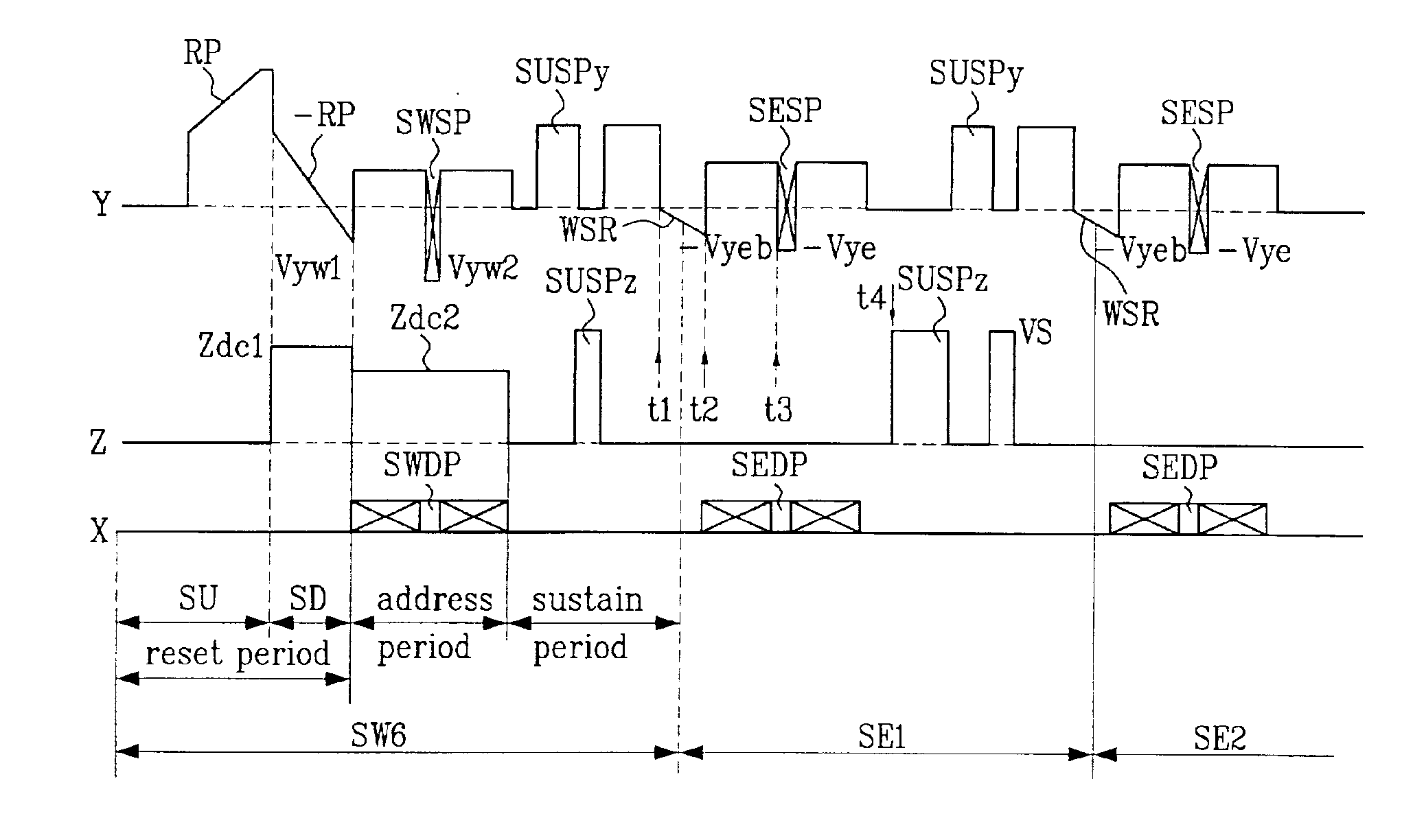
However, if the sustain voltage Vs of the sustain pulses SUSPy and SUSPz is too high, or the selective erase scan voltage −Vye is too low, an erratic discharge is occurred at the time point t2, when it is required that no discharge is occurred.

Method used


Image

  • Method for driving plasma display panel
  • Method for driving plasma display panel
  • Method for driving plasma display panel

Examples


Embodiment Construction

Reference will now be made in detail to the preferred embodiments of the present invention, examples of which are illustrated in the accompanying drawings FIGS. 6˜8. Though only a case when one time frame is divided into 12 sub-fields SF1˜SF12 in operation of an AC PDP of surface discharge type having 3-electrodes hereafter, the present invention is not limited only to the case the frame is divided into 12 sub-frames. FIG. 6 illustrates a waveform diagram showing operative waveforms of a PDP in accordance with a first preferred embodiment of the present invention.

Referring to FIG. 6, in the reset period of the sixth selective write sub-field SW6, the last selective write sub-field, a reset pulse of ramp-up waveform RP is provided to the scan electrode lines Y in an initial set-up period SU. The reset pulse of ramp-up waveform RP causes a set-up discharge in discharge cells on entire screen, to accumulate wall charges of positive polarity (+) on the address electrode lines X and the ...


PUM


Abstract

Method for driving a plasma display panel, wherein a pulse of ramp-down waveform is applied to scan electrode lines between a sustain period of a last selective write sub-field and an address period of a first selective erase sub-field continuous thereto, or between the sustain period of a preceding selective erase sub-field and the address period of a next selective erase sub-field continuous thereto after the first selective erase sub-field, whereby causing more stable address discharge at a higher sustain voltage, or a lower selective erase scan voltage.

Description

This application claims the benefit of the Korean Application No. P2002-18544 filed on Apr. 4, 2002, which is hereby incorporated by reference.BACKGROUND OF THE INVENTION1. Field of the InventionThe present invention relates to a plasma display panel, and more particularly, to a method for driving a plasma display panel, for making a stable address discharge.2. Background of the Related ArtThe plasma display panel (hereafter called as “PDP”) is a device for displaying a picture including characters, or graphics by making phosphor luminescent by a UV ray emitted when inert gas mixture (He+Xe, Ne+Xe, or He+Xe+Ne) discharges. The PDP has advantages in that fabrication of a large sized thin screen is easy, and provides a significantly improved picture quality owing to recent technical development.Typically, the PDP is provided with three electrodes driven by an AC voltage, which is called as an AC surface discharge type PDP. The AC surface discharge type PDP has advantages of a low volt...

Claims


Application Information

Patent Timeline
Patent Type & Authority Patents(United States)
IPC IPC(8): G09G3/28G09G3/20H04N5/66G09G3/288G09G3/291G09G3/292G09G3/293G09G3/294G09G3/298
CPCG09G3/2022G09G3/2927G09G3/2935G09G3/2932G09G2320/0238G09G2310/066G09G3/296
Inventor MYOUNG, DAEJINKIM, TAE HYUNGKIM, DAI HYUNKWAK, JONG WOONLIM, GEUN SOO
Owner LG ELECTRONICS INC
Learn More