Architecture for real-time texture look up's for volume rendering

a volume rendering and texture technology, applied in the field of visualization methods, can solve the problems of inability to see the interior of the volume 3d, inability to obtain new information, and computational costs, and achieve the effects of reducing the burden on available hardware resources, fast texture lookup updates, and efficient software data structur

Inactive Publication Date: 2005-04-05
ROUND ROCK RES LLC
View PDF3 Cites 28 Cited by
  • Summary
  • Abstract
  • Description
  • Claims
  • Application Information

AI Technical Summary

Benefits of technology

The present invention is an algorithm that enables fast texture lookup updates to volume rendered datasets. The present invention accomplishes this using an efficient software data structure that reduces the burden on the available hardware resources thereby increasing efficiency and throughput. This feature is particularly valuable for a wide range of volume rendering applications. For example, the present invention will aid quick diagnosis in medical imaging applications, efficient seismic interpretation in geophysical applications, and even allow for fine tuning of rendering parameters to achieve artistic and emotional appeal in applications related to the creation of special effects, e.g. water, smoke, fire, etc. for entertainment applications. Those, and other advantages and benefits, will be apparent from the

Problems solved by technology

Unfortunately, it is difficult to see the 3-dimensional structure of the interior of volumes by viewing individual slices.
While slicing is possible on traditional 3D models, the lack of any information on the internal structure means that no new information is to be had by slicing and viewing the internals.
Another drawback of these techniques is their computational cost.
As a result, real-time imaging becomes problematic with large datasets.
However, oftentimes anatomically distinct regions are not entirely homogeneous.
The problem is to identify this range accurately.

Method used


Image

  • Architecture for real-time texture look up's for volume rendering
  • Architecture for real-time texture look up's for volume rendering
  • Architecture for real-time texture look up's for volume rendering

Examples


Embodiment Construction

The present invention addresses the problem of interactive updates to texture lookup tables that are defined for volumetric datasets which in turn enables real-time updates to the rendered volumetric image. Volume datasets are scalar or vector density fields defined over a 3D grid. The individual scalar values at each grid point are called a voxel. As mentioned, volume datasets are available from many different sources such as medical scanners (MRI and CT), spectrum analyzers, laser stripe triangulators, and from various types of computations such as finite element analyses. By interactive and real-time updates I mean the update of the lookup table with a new set of color and opacity values that would result in a re-rendered volumetric image at rates that are fast enough for the user to perceive little or no lag between the inception of the update and the actual refresh of the rendered image.

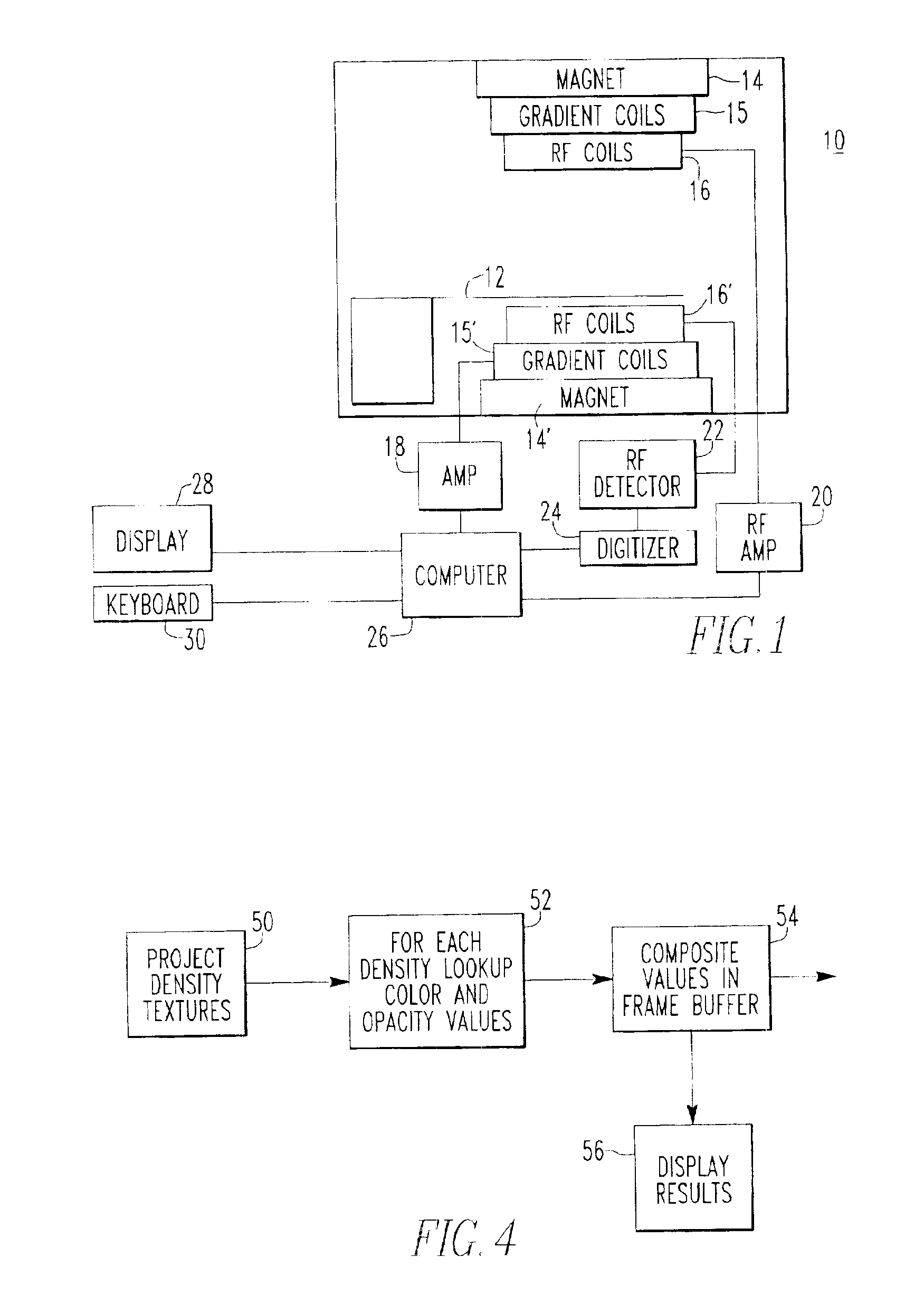
The present invention will now be described in connection with an MRI apparatus 10 illustrat...


PUM


Abstract

A slice plane, oriented parallel to a viewing plane, is passed through a cuboidal dataset at regular intervals. The intersection of the slice plane with the cuboidal volume dataset results in primitives (quads, triangles, etc. depending on the angle and position of the intersection) whose vertices have position coordinates (xu, yu, zu) and 3D-texture coordinates (r, s, t). The resulting primitives are rasterized using, for example, a traditional 3D graphics pipeline wherein the 3D-texture coordinates are interpolated across the scanlines producing 3D-texture coordinates for each fragment. The resulting 3D-texture coordinates for each fragment are stored in a 2D-texture storage area. These 2D-textures are called density-textures. By preprocessing the cuboidal dataset, the rendering process becomes a compositing process. A rendering process is comprised of looking-up, for each densel in the texture, the corresponding color and opacity values in the current lookup-table. A user-specified compositing function is used to blend the values with those in the framebuffer to arrive at the final result. The final result, i.e. the values in the framebuffer, is displayed.

Description

BACKGROUND OF THE INVENTION1. Field of the InventionThe present invention is directed to visualization methods and, more particularly, to volume-rendering techniques.2. Description of the BackgroundThe increasing availability of powerful workstations has fueled the development of new methods for visualizing or rendering volumetric datasets. Volumetric datasets are scalar or vector density fields defined over a 3D grid. The individual scalar values at each grid point is called a voxel. Typically, volumetric datasets are available from many different sources such as:medical scanners such as magnetic resonance imagers (MRI) and computed tomography (CT);sound spectrum analyzers which may produce seismic data;laser strip triagulators which may produce height field data; andfluid dynamics data from discretization of 3D Navier-Stokes' partial-differential equations describing fluid flow.Astrophysical, meteorological and geophysical measurements, and computer simulations using finite elemen...

Claims


Application Information

Patent Timeline
Patent Type & Authority Patents(United States)
IPC IPC(8): G06T15/20G06T15/10G06T15/04
CPCG06T15/04
Inventor VENKATARAMAN, KARTIK
Owner ROUND ROCK RES LLC
Why Eureka
Try Eureka