
Microchannel plate having microchannels with deep funneled and/or step funneled openings and method of manufacturing same

a microchannel plate and microchannel technology, applied in the field of microchannel plates, can solve the problems of reduced viewer's ability to discriminate image detail, image noise, and output image not being a perfect replica of the input imag

Inactive Publication Date: 2005-04-05
EXCELIS INC
View PDF6 Cites 9 Cited by
  • Summary
  • Abstract
  • Description
  • Claims
  • Application Information

AI Technical Summary

Benefits of technology

"The present invention provides an improved microchannel plate for an image intensifier tube. The microchannel plate includes multiple microchannels with a unique design that allows for improved performance. The microchannels have a first portion with a wider opening and a second portion with a conical shape that tapers towards a smaller opening. The microchannels also have a third portion with a similar cross-sectional diameter to the second opening and a fourth portion with a narrower opening. The invention also includes a method for making the microchannel plate. The technical effects of this design include improved image quality, reduced noise, and improved durability."

Problems solved by technology

That is, the output image is not a perfect replica of the input image.
A net effect is a slight out-of-focus condition that reduces a viewer's ability to discriminate detail of an image.
The amplification factor for such spurious electrons is the same as the amplification factor for the image electrons, and results in image noise manifested as flickering points of light in the image.
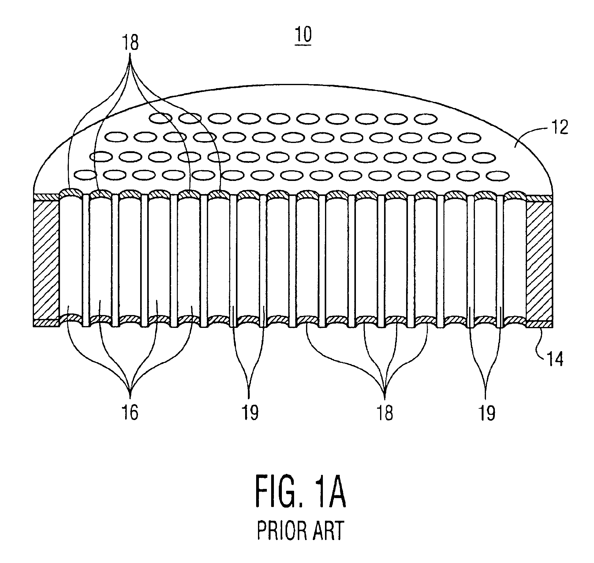
Higher open-area ratios are desirable, but unfortunately, a MCP that has parallel surfaces is limited to an open-area ratio of approximately 65%, so that sufficient glass remains for structural integrity.
Reduction of input electron collection efficiency also reduces performance of the image intensifier tube by lowering its signal-to-noise ratio.

Method used


Image

  • Microchannel plate having microchannels with deep funneled and/or step funneled openings and method of manufacturing same
  • Microchannel plate having microchannels with deep funneled and/or step funneled openings and method of manufacturing same
  • Microchannel plate having microchannels with deep funneled and/or step funneled openings and method of manufacturing same

Examples


Embodiment Construction

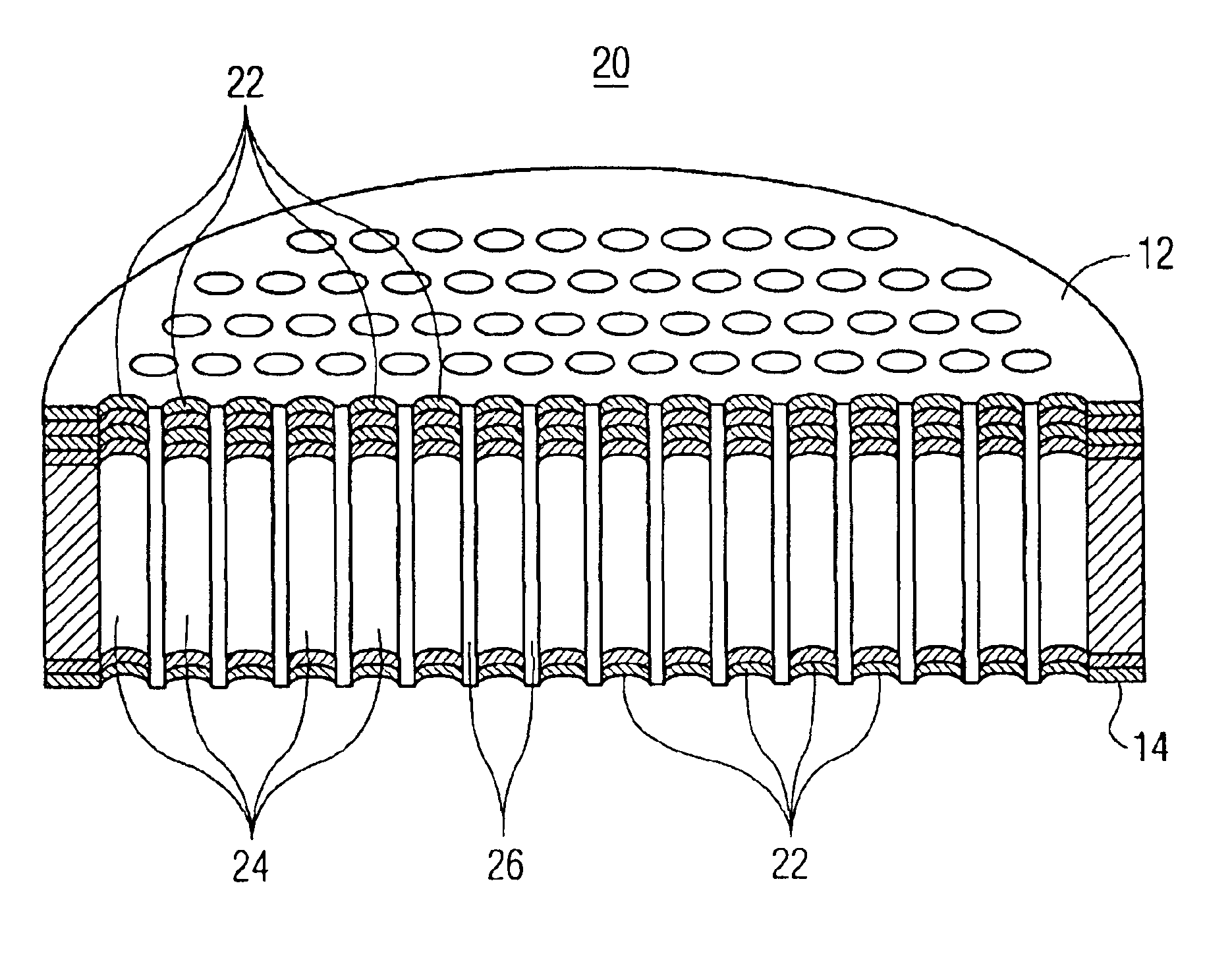
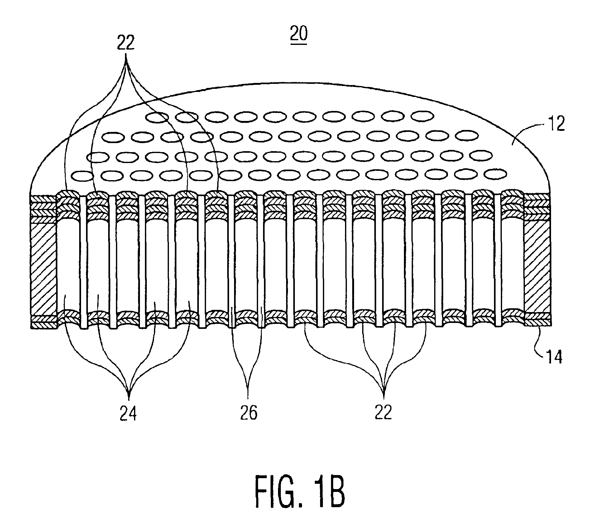
In accordance with the present invention, a microchannel plate (MCP) having deep funneled openings and / or step funneled openings overcomes the disadvantages caused by metallization of exposed microchannels at the input side or output side of the MCP. By moving the funnel deeper into the MCP microchannel (or further away from the input / output side), performance of the MCP is enhanced and not degraded by any metallization process. Incident electrons are less likely to encounter metal coatings in a deep funnel channel, as they may in a fully straight channel of a similar diameter.

In addition, although the deep funnel channel has a wider diameter than either a non-funneled channel or a basic-funneled channel (basic-funnel disclosed in U.S. Pat. No. 6,311,001), the deep funnel channel retains sufficient wall thickness along most of its length (for example 90% of its length) and provides strength and rigidity to the MCP.

Referring to FIG. 1B, there is shown a sectional view of MCP 20, form...


PUM


Abstract

The invention includes a microchannel plate for an image intensifier tube, in which the plate has multiple microchannels extending in a longitudinal dimension between transverse surfaces of the plate. Each microchannel includes a first portion forming a first opening at an end proximate a surface of the plate. The first portion includes a wall extending longitudinally from the surface and terminating in a substantially similar first opening at a distal end. The microchannel also includes a second portion of the wall, extending longitudinally from the first opening at the distal end and tapering toward a second opening at a further distal end. The first opening at the proximate end has a diameter that is substantially similar to a diameter of the first opening at the distal end. The first opening is also wider than the second opening.

Description

FIELD OF THE INVENTIONThis invention relates, in general, to microchannel plates for use in image intensifier tubes, and in particular, to a microchannel plate having microchannels with deep funneled openings and / or step funneled openings.BACKGROUND OF THE INVENTIONImage intensifier tubes are used in night / low light vision applications to amplify ambient light into a useful image. A typical image intensifier tube is a vacuum device, roughly cylindrical in shape, and generally includes a body, photocathode and faceplate, microchannel plate (MCP), and output optic and phosphor screen. Incoming photons are focused on the glass faceplate by external optics, and strike the photocathode that is bonded to the inside surface of the faceplate. The photocathode converts the photons to electrons, which are accelerated toward the MCP by an electric field. The MCP has many microchannels, each of which functions as an independent electron amplifier, and roughly corresponds to a pixel of a CRT. Th...

Claims


Application Information

Patent Timeline
Patent Type & Authority Patents(United States)
IPC IPC(8): G02B6/06G02B6/08
CPCG02B6/08H01J43/246H01J31/507
Inventor ROSINE, STEVEN DAVIDDEVOE, NELSON CHRISTOPHER
Owner EXCELIS INC
Learn More