Testing compliance of a device with a bus protocol

a technology of bus protocol and device, applied in the direction of transmission, instruments, electric digital data processing, etc., can solve the problems of time-consuming and labor-intensive process of testing a specific master device or slave device, or a combination of master and slave device, and can be very costly to perform the test procedure on the componen

Inactive Publication Date: 2005-04-05
ARM LTD
View PDF6 Cites 91 Cited by
  • Summary
  • Abstract
  • Description
  • Claims
  • Application Information

AI Technical Summary

Benefits of technology

[0026]In preferred embodiments, the set of coverage points is configured dependent on the configuration file read at step (a) of the testing method. Hence, since any particular device being tested may not use all aspects of the bus protocol, the coverage points can be tailored based on the configuration file to identify a set of coverage points relevant to the device being tested. The advantage of using coverage points instead of a standard pre-defined sequence of bus transactions is that such an approach allows for the fact that a particular device may require a specific sequence of transactions in order to fully exercise the bus interface.

Problems solved by technology

It would clearly be very costly to perform test procedures on the component once it has actually been reduced to hardware, and instead rigorous testing of the RTL representation of the component is typically performed to ensure that the actual hardware generated from that RTL representation will operate correctly.
This approach is less satisfactory than either of the two earlier described approaches, since it is typically relatively slow, and does not monitor the bus protocol directly, but rather makes assumptions about compliance with the bus protocol by monitoring results of actions invoked via the bus.
As will be appreciated by those skilled in the art, when using any of the techniques described above, the process of testing a specific master device or slave device, or a combination of master and slave devices, is a time consuming process, especially considering the numerous configurations and capabilities of each device, for example a master device that can only support incrementing bursts, a slave device that is not capable of accepting write transactions, etc.
Further, when certain bus activity is required to be observed such as a bus handover or an early burst termination, this can be quite difficult to provoke without dedicated RTL to perform the task, thus adding to the time required to design and verify a device.

Method used


Image

  • Testing compliance of a device with a bus protocol
  • Testing compliance of a device with a bus protocol
  • Testing compliance of a device with a bus protocol

Examples


Embodiment Construction

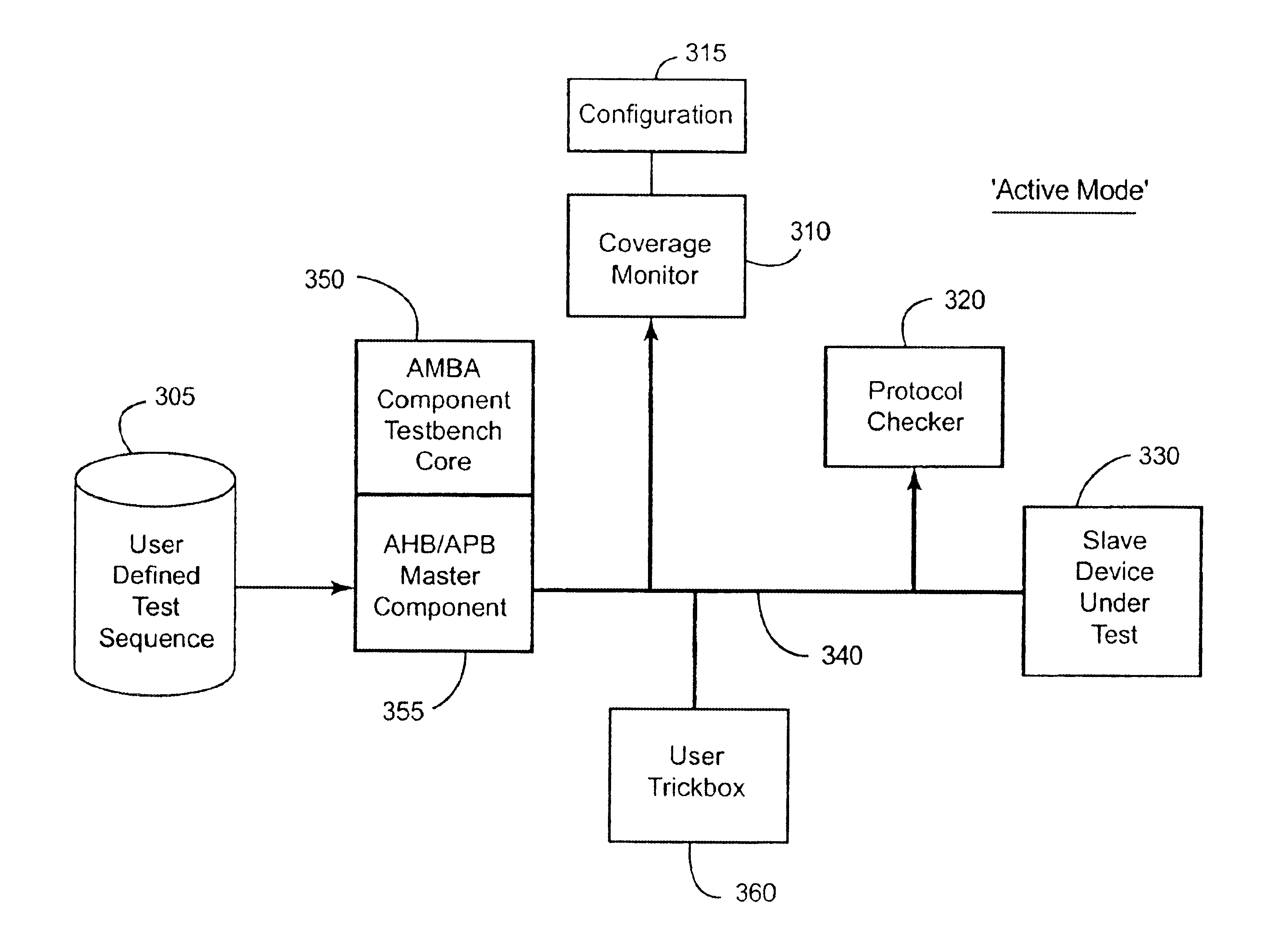
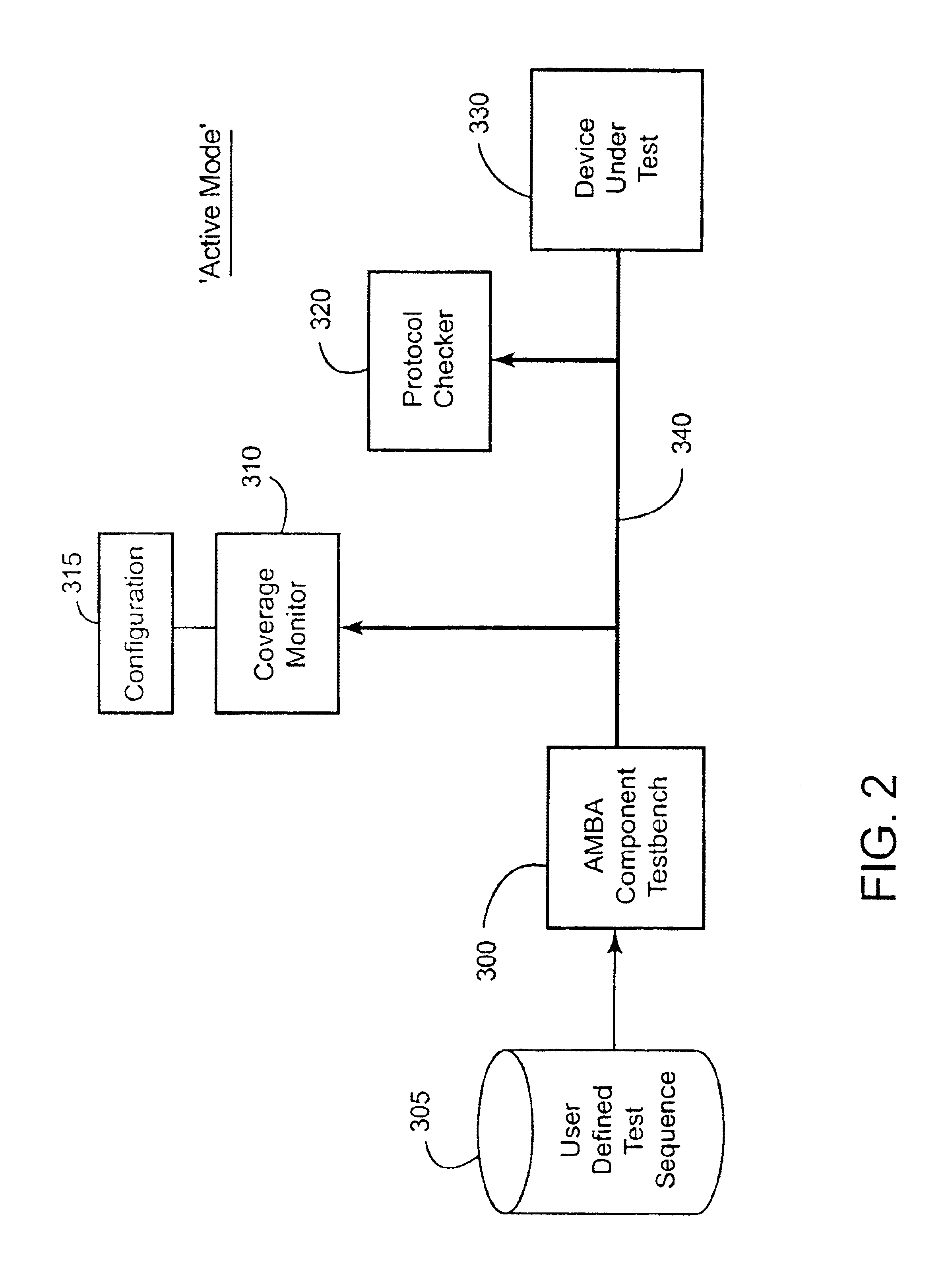
agram illustrating more detail of the logical elements used in the active mode of preferred embodiments when testing a slave device;

[0044]FIG. 4 is a block diagram illustrating more detail of the logical elements used in an active mode of preferred embodiments when testing a master device;

[0045]FIG. 5 is a block diagram schematically illustrating the logical elements used when performing testing in accordance with a passive mode of preferred embodiments of the present invention;

[0046]FIG. 6 is a flow diagram illustrating the steps performed to execute a compliance check in accordance with preferred embodiments of the present invention;

[0047]FIG. 7 is a block diagram illustrating in more detail the process of generating a compliance test environment for the device under test;

[0048]FIG. 8 is an example graphical notation used to represent evaluation of temporal sequences when performing protocol checking in accordance with preferred embodiments of the present invention;

[0049]FIGS. 9A ...


PUM


Abstract

The present invention provides a system and method for testing compliance of a device with a bus protocol. The method comprises the steps of reading a configuration file containing predetermined parameters identifying the type of device and capabilities of the device, and then employing a configuration engine to dynamically generate a test environment for the device by creating selected test components which are coupled via the bus with a representation of the device to form the test environment, the test components being selected dependent on the configuration file. A test sequence is then executed, during which signals passed between the representation of the device and one or more of the test components are monitored to generate result data indicating compliance with the bus protocol. This approach has been found to provide a particularly user friendly and efficient approach for testing compliance of devices with a bus protocol.

Description

[0002]This application claim priorities to UK Application No. 0109283.2 filed 12 Apr. 2001 and UK Application No. 0111195.4 filed 8 May 2001. The entire contents of these applications are incorporated herein by reference.BACKGROUND OF THE INVENTION[0003]1. Field of the Invention[0004]The present invention relates to techniques for testing compliance of a device with a bus protocol.[0005]2. Description of the Prior Art[0006]When developing components for integration into a system, a number of test procedures are typically performed to ensure that the component will operate in the desired manner when integrated into the system. Often the system will consist of a number of individual components connected together via one or more buses. The bus specification will often provide a standard interface to each component, and hence enables the component supplier to design and test the component without any knowledge of the system into which the component will finally be integrated.[0007]Howev...

Claims


Application Information

Patent Timeline
Patent Type & Authority Patents(United States)
IPC IPC(8): H04L12/26G06F13/00H04L12/40
CPCH04L43/50H04L12/2697
Inventor NIGHTINGALE, ANDREW MARK
Owner ARM LTD
Why Eureka
Try Eureka