Front retracting plow

a plow and front technology, applied in the field of plow blades, can solve the problems of high price, inability to safely drive the wide blade from one site to another, and inability to maximize the width of the blade, so as to reduce the profile of the blad

Inactive Publication Date: 2005-04-12
AGWAY MFG
View PDF12 Cites 37 Cited by
  • Summary
  • Abstract
  • Description
  • Claims
  • Application Information

AI Technical Summary

Benefits of technology

In an aspect of the present invention, each pivoting connector includes a hydraulic actuator operatively connected for effecting movement between the retracted and extended positions. In an aspect of the present invention, each of the bars of the parallel arm linkages connect at points vertically spaced sufficient to resist torsional forces of the wing blades in relation to the main blade. In an aspect of the present invention, the vehicle mount enables the plow to be rotated in a horizontal plane to allow for inclination of the blades from the vehicles forward direction and a smaller transport profile.
By retracting one or more of the wing blades in front of the main blade, the plow is able to provide a reduced blade profile, while providing a transport width that enables transit between worksites over standard roads. At the same time the invention avoids the problems inherent in many prior art plows, where the retracting of wing blades behind the main blade introduces the risk of tire damage by having a sharp blade next to vulnerable tires.

Problems solved by technology

This can especially be the case for airport runways, where for safety reasons snow removal crews must adhere to guidelines on permissible snow accumulations, and time spent by an airliner sitting on a taxiway awaiting the removal of snow from a runway is highly expensive.
The problem is that maximizing blade widths is in direct conflict with a need to minimize that same blade for safe transport between worksites.
With most snowplows typically mounted to multipurpose vehicles such as front-end loaders, wide blades cannot safely be driven from one site to another.
These however involve complex components, and are prone to clogging and icing up.
The problem with this rearward-retracting configuration is that the wing blades must be tucked behind the main blade and are therefore in front of and adjacent to the tires of the host vehicle, making the retracted position of the wing blades proximal to the tires, thus creating a safety hazard.

Method used


Image

  • Front retracting plow
  • Front retracting plow
  • Front retracting plow

Examples


Embodiment Construction

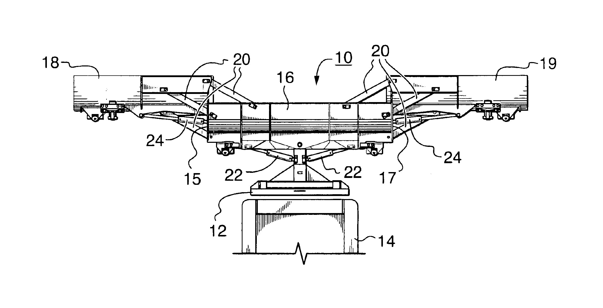
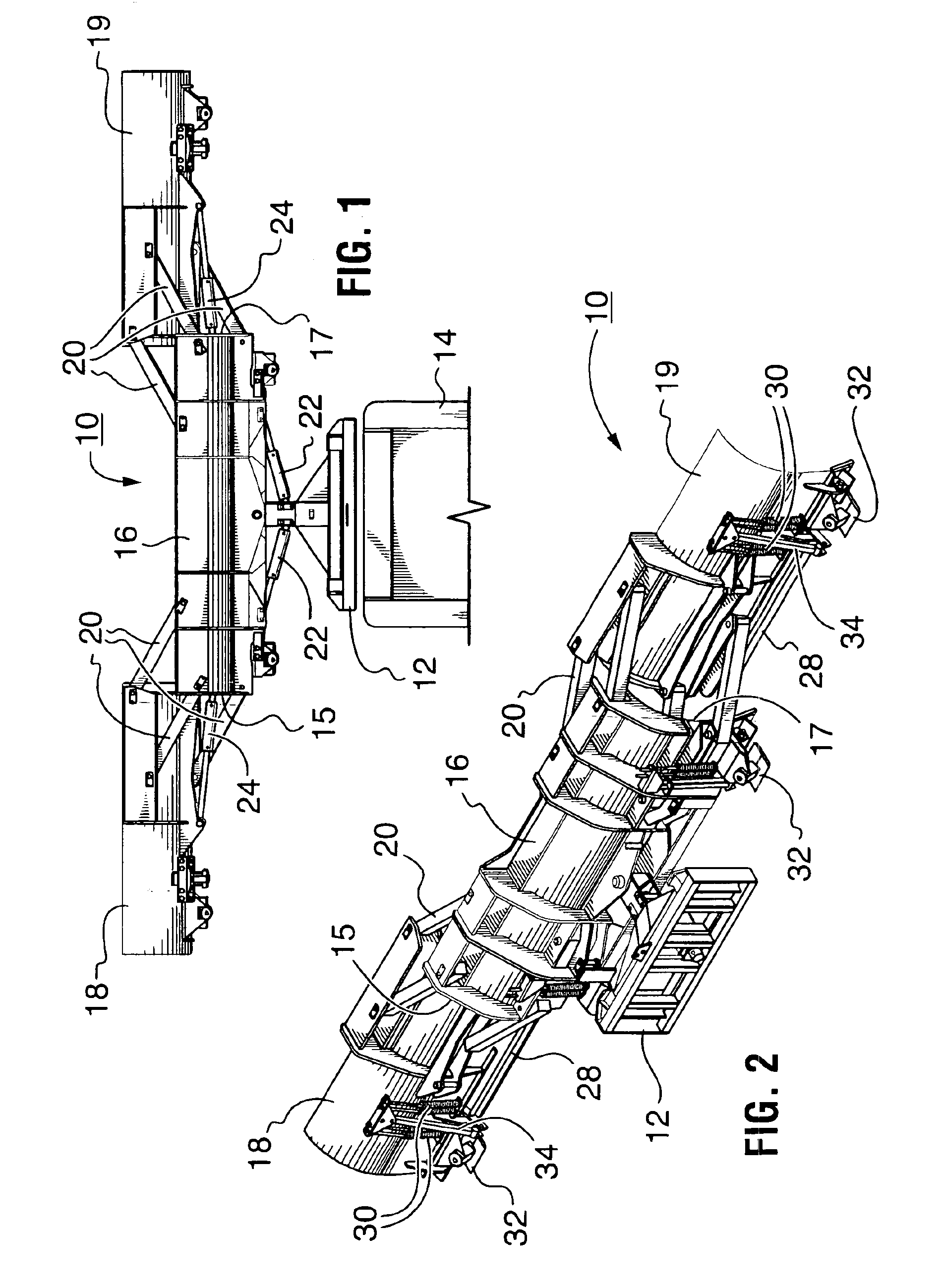
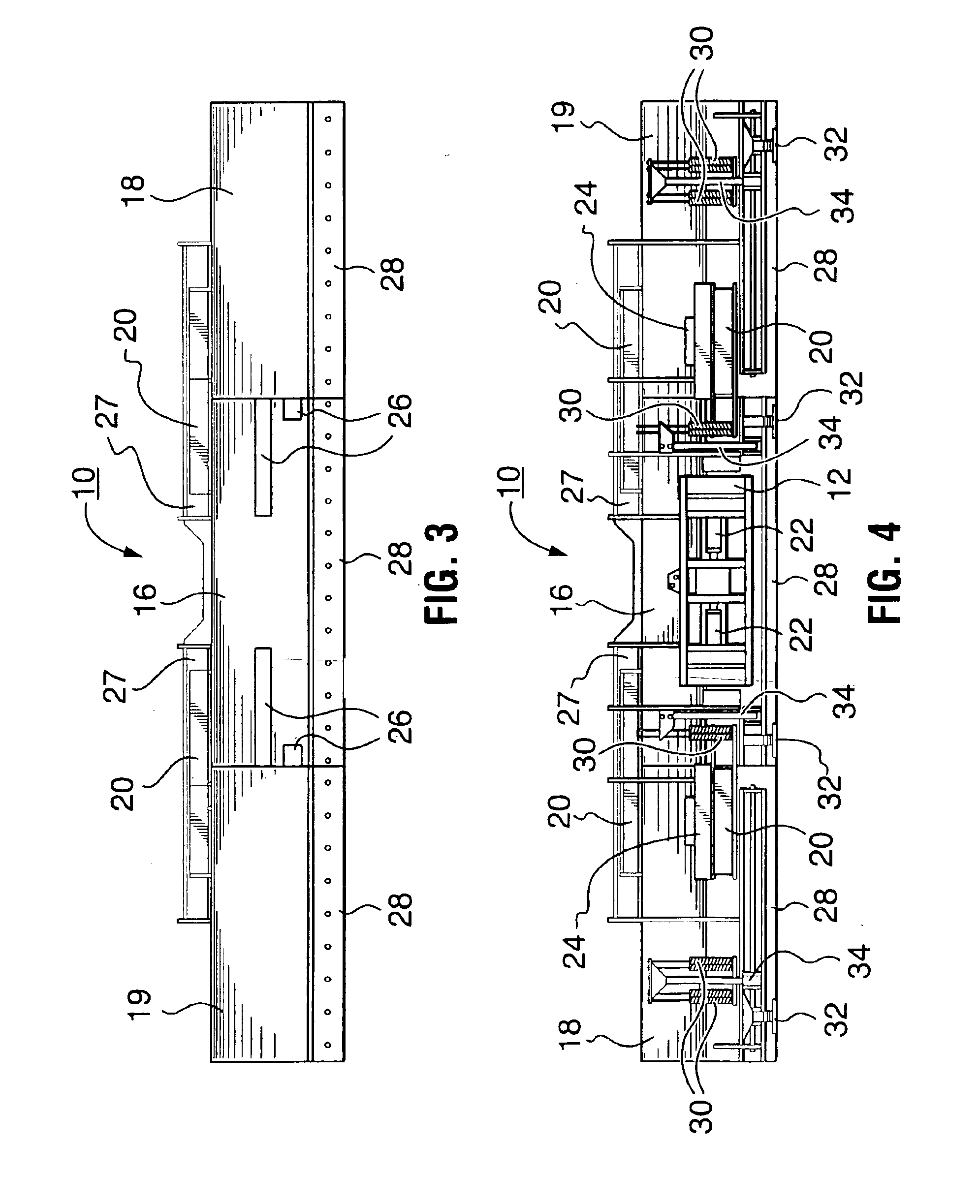
The present invention is directed to a front-retracting plow 10. As illustrated in FIG. 1, the plow 10 includes a vehicle mount 12 for mounting the plow 10 to a host vehicle 14. A main blade 16 is mounted to the vehicle mount 12, and a left wing blade 18 and a right wing blade 19 are pivotally mounted to the left and right opposing ends 15 and 17 respectively of the main blade 16. The plow 10 further includes four bar parallel arm linkages 20 and hydraulic actuators 22 connected between opposing ends of the main blade 16 and each of the wing blades 18 and 19 for moving the wing blades 18 and 19 between retracted positions in front of and in close proximity to the main blade 16 and extended positions in longitudinal alignment with the main blade 16 and in end-to-end relation therewith, whereby a plurality of plowing widths is provided.

The main blade 16 is pivotally mounted to the vehicle mount 12 to allow inclination of the plow 10 through the horizontal plane, enabling plowing at va...


PUM


Abstract

The plow includes a vehicle mount for mounting the plow to a host vehicle, and a main blade mounted to the vehicle mount The plow further includes a pair of wing blades pivotally mounted to the main blade for travel in an arcuate path relative to the main blade, and four bar parallel arm linkages and actuators connected between opposing ends of the main blade and each of the wing blades for supporting and swinging the at least one wing blade in said arcuate travel path throughout the full distance between a retracted position in front of the main blade such that at least a substantial portion of the at least one wing blade is disposed in overlapping relation with the main blade, and an extended position in substantial longitudinal alignment with the main blade whereby a plurality of plowing widths is provided. It should be noted that the blade is advantageously used for the plowing of snow, however the plowing of other materials is envisioned such as sand or gravel.

Description

FIELD OF THE INVENTIONThe present invention relates generally to plowing equipment, and more particularly to a retracting plow blade.BACKGROUND OF THE INVENTIONIn northern climates, snowplows wider than the standard plows used on highways and surface streets are required for the plowing of large areas such as parking lots and airport runways. As such, it is desirable to be able to plow as wide a swath as possible in one pass to minimize the time it takes to complete the plowing of an area. This can especially be the case for airport runways, where for safety reasons snow removal crews must adhere to guidelines on permissible snow accumulations, and time spent by an airliner sitting on a taxiway awaiting the removal of snow from a runway is highly expensive.A traditional method of plowing a wide swath has simply been to maximize the width of a host vehicle mounted fixed blade. The problem is that maximizing blade widths is in direct conflict with a need to minimize that same blade fo...

Claims


Application Information

Patent Timeline
Patent Type & Authority Patents(United States)
IPC IPC(8): E01H5/06E01H5/04
CPCE01H5/065E01H5/06
Inventor FREY, OSCAR
Owner AGWAY MFG
Why Eureka
Try Eureka