Vehicle fuel management system

a fuel management system and vehicle fuel technology, applied in the direction of machines/engines, electric control, combustion air/fuel air treatment, etc., can solve the problems of unfavorable fuel pump operation, continued full speed operation of fuel pump further consume electrical energy, unwanted gas vapor, etc., and achieve cost-effective control

Inactive Publication Date: 2005-04-12
UUSI
View PDF22 Cites 95 Cited by
  • Summary
  • Abstract
  • Description
  • Claims
  • Application Information

AI Technical Summary

Benefits of technology

According to one aspect of the present invention, an integrated fuel management system and method are provided that offer cost affordable controls for controlling the fuel storage and delivery in a vehicle. The fuel management system includes a fuel storage tank for storing fuel in a vehicle, and a vapor collection canister coupled to the fuel storage tank for collecting fuel vapor. A vent actuator is coupled to the vapor collection canister for venting gas from the canister during a vent operation. A purge actuator is also coupled to the vapor coll

Problems solved by technology

This results in a continuous audible noise which can be noticeable to vehicle occupants, particularly when the engine is operated at low engine load demands, e.g., engine idle speed.
Continued full speed operation of the fuel pump further consumes electrical energy, which could otherwise be made available elsewhere to enhance the vehicle energy efficiency.
Additionally, the return of a large amount of excessive fuel through the regulator to the fuel storage tank may cause heating of the fuel that, in turn, creates unwanted gas vapor, which adds to evaporative emissions, and which then must be vented through a charcoal canister.
Many such fuel deliver

Method used


Image

  • Vehicle fuel management system
  • Vehicle fuel management system
  • Vehicle fuel management system

Examples


first embodiment

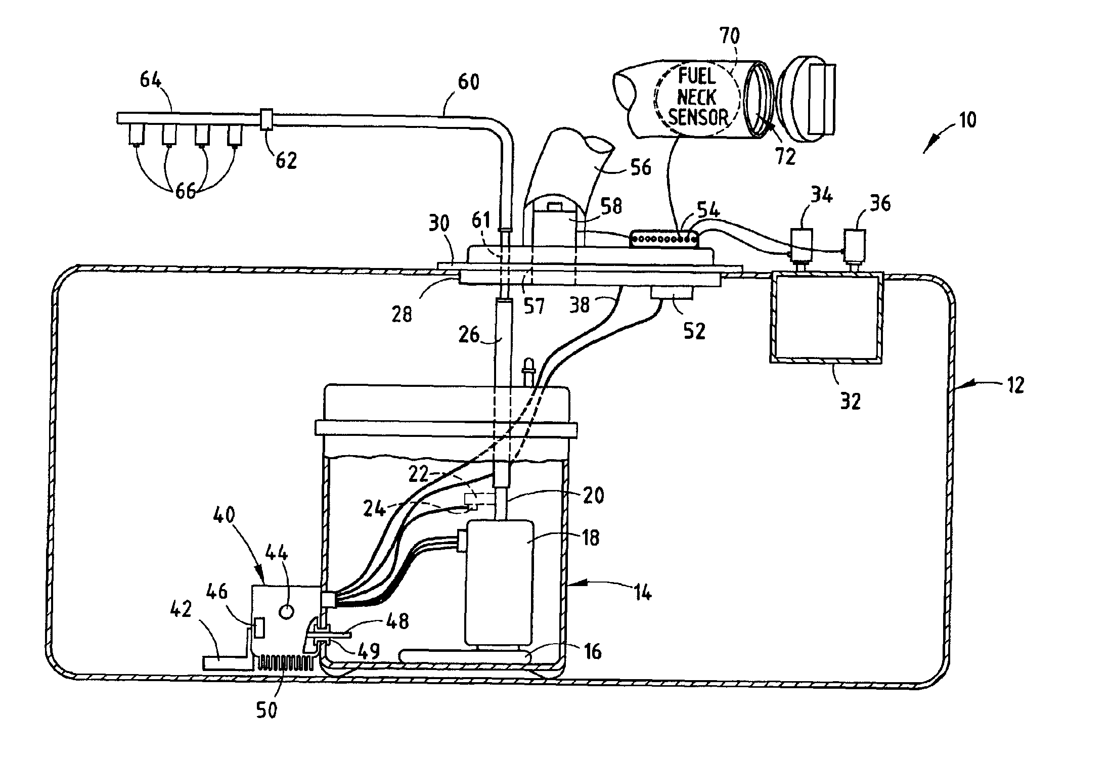
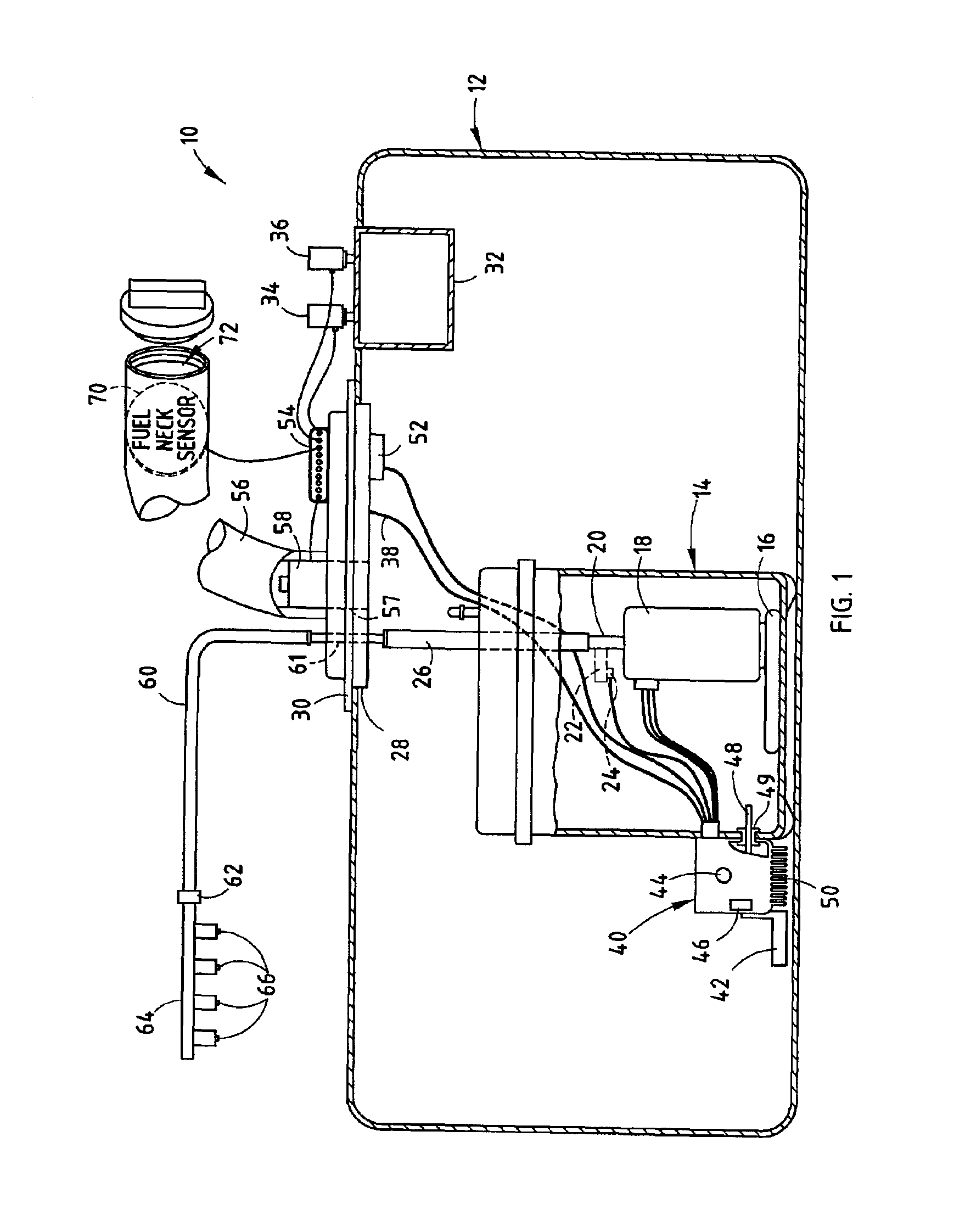
Referring to FIG. 1, the vehicle fuel management system 10 is generally illustrated for use in on-board management and control of fuel for an engine in an automotive vehicle. The vehicle fuel management system 10 integrates various fuel related functions generally associated with the fill, storage, and delivery of fuel to the engine in an automotive vehicle. The vehicle fuel management system 10 includes a fuel delivery system for delivering fuel from a fuel storage tank 12 to a fuel rail 64 associated with the vehicle engine. The vehicle fuel management system 10 also controls the fuel fill operation to fill and store fuel in the fuel storage tank 12. Further, the fuel management system 10 controls the fuel vapor vent and purge operations to vent pressurized gas and purge evaporated vapor emissions from a fuel collection canister, respectively. The various fuel related functions performed by the fuel management system 10 are integrated together and are adapted to be controlled loca...

second embodiment

the fuel management system 10 is illustrated in FIGS. 5 and 6 with the fuel control module 40 mounted to the fuel reservoir assembly 14, absent the return path 22 and pressure sensor 24 shown in the first embodiment. The fuel management system 10 of the second embodiment has no return path for returning fuel back into the fuel reservoir assembly 14, and thus is a returnless fuel delivery system. Instead, the fuel that is pumped into the pump outlet 20 is passed through both fuel delivery line 26 and chassis line 60 and is supplied to the fuel rail 64.

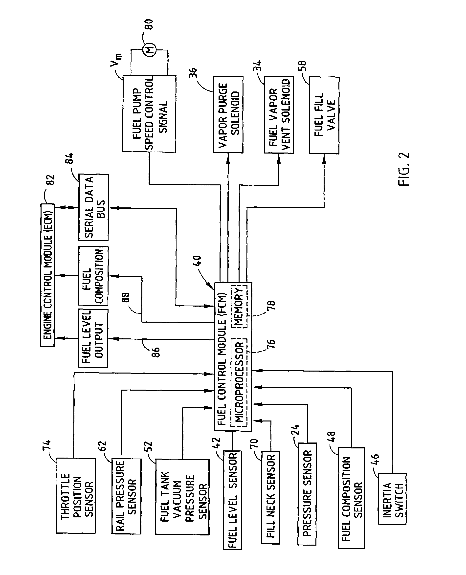
As shown in FIG. 6, the fuel rail pressure sensed at the fuel rail 64 via pressure sensor 62 is provided as an input to the engine control module 82. The engine control module 82 generates a pulse-width modulated (PWM) output command signal via control logic 90 and transistor 92 that is communicated as a command signal to the fuel control module 40. The engine control module 82 has a microprocessor and memory containing the control logi...

fourth embodiment

the fuel management system 10 showing yet a further fuel delivery system is illustrated in FIGS. 11 and 12. In FIG. 11, the fuel management system 10 is shown having the fuel control module 40 disposed within the fuel storage tank 12 and connected to the fuel reservoir assembly 14. In this embodiment, the outlet 20 of the variable speed fuel pump 18 is configured to pass through a flow path 45 provided internal to the fuel control module 14 which, in turn, is connected to the fuel delivery line 26. Disposed in communication with the internal flow path 45 and module 40 is the flow sensor 124 (see FIG. 12) integrally mounted within the fuel control module 40. The flow sensor 124 monitors the rate of flow of fuel through flow passage 45 internal to the fuel control module 40. Accordingly, by employing a flow sensor 124 internal to fuel control module 40, a reduction in the wires and external components is achieved.

Referring particularly to FIG. 12, the fourth embodiment of the fuel man...


PUM


Abstract

An integrated fuel management system and method for controlling the fuel storage and delivery in a vehicle. The fuel management system includes a fuel storage tank for storing fuel in a vehicle, a vapor collection canister located within the fuel storage tank, a vent actuator coupled to the vapor collection canister for venting gas from the canister during a vent operation, and a purge actuator coupled to the canister for purging fuel vapor from the canister during a purge operation. A variable speed fuel pump is disposed within the fuel storage tank for delivering fuel to a fuel delivery line for an engine. The fuel management system has a controller provided in a module disposed in communication with the fuel for controlling the amount of fuel pumped with the variable speed fuel pump to deliver fuel to the fuel delivery line and further control the purge and vent actuators.

Description

BACKGROUND OF THE INVENTIONThe present invention generally relates to on-board fuel storage and delivery to an engine in a vehicle and, more particularly, relates to vehicle fuel management for controlling fuel storage and delivery to the engine.Automotive vehicles are typically powered by an internal combustion engine that converts the chemical energy of a fuel (e.g., gasoline) to mechanical energy for driving a powertrain which, in turn, propels the vehicle via road wheels. Additionally, some of the mechanical energy is also converted to electrical energy via an alternator and is stored in a battery and used to power various electrically operated devices. Vehicles are being equipped with increasing numbers of electrically powered devices, all of which consume energy. Thus, it is desirable to enhance the efficiency of the electrically powered devices in order to maximize the overall energy efficiency of the vehicle.Automotive vehicles employ a fuel storage tank and a fuel delivery ...

Claims


Application Information

Patent Timeline
IPC IPC(8): B60K15/035B60K15/03F02D41/00F02D41/30F02M25/08F02D41/26F02M37/10F02M37/08F02D41/38
CPCB60K15/03504B60K15/03519F02D41/0032F02M37/106F02D41/266F02D41/3082F02M25/08F02M25/089F02M37/0082F02D41/0045B60K2015/0319B60K2015/03557F02D41/003F02D41/3809
Inventor WASHELESKI, JOHNPERRIN, RANDALL L.MITCHELL, JOHN E.
Owner UUSI
Why Eureka
Try Eureka