Gravel packing method using vibration and hydraulic fracturing
- Summary
- Abstract
- Description
- Claims
- Application Information
AI Technical Summary
Benefits of technology
Problems solved by technology
Method used
Image
Examples
Embodiment Construction
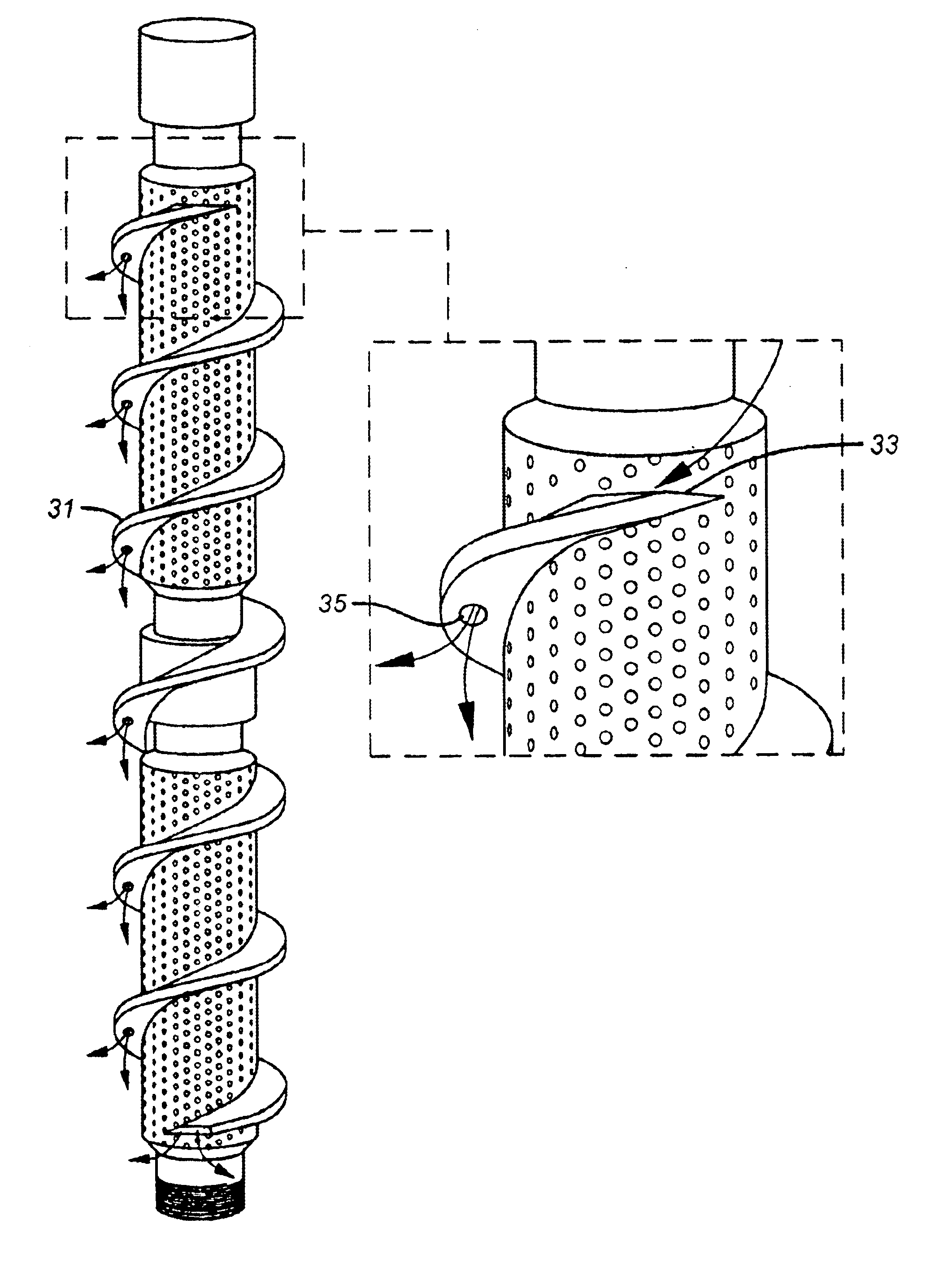
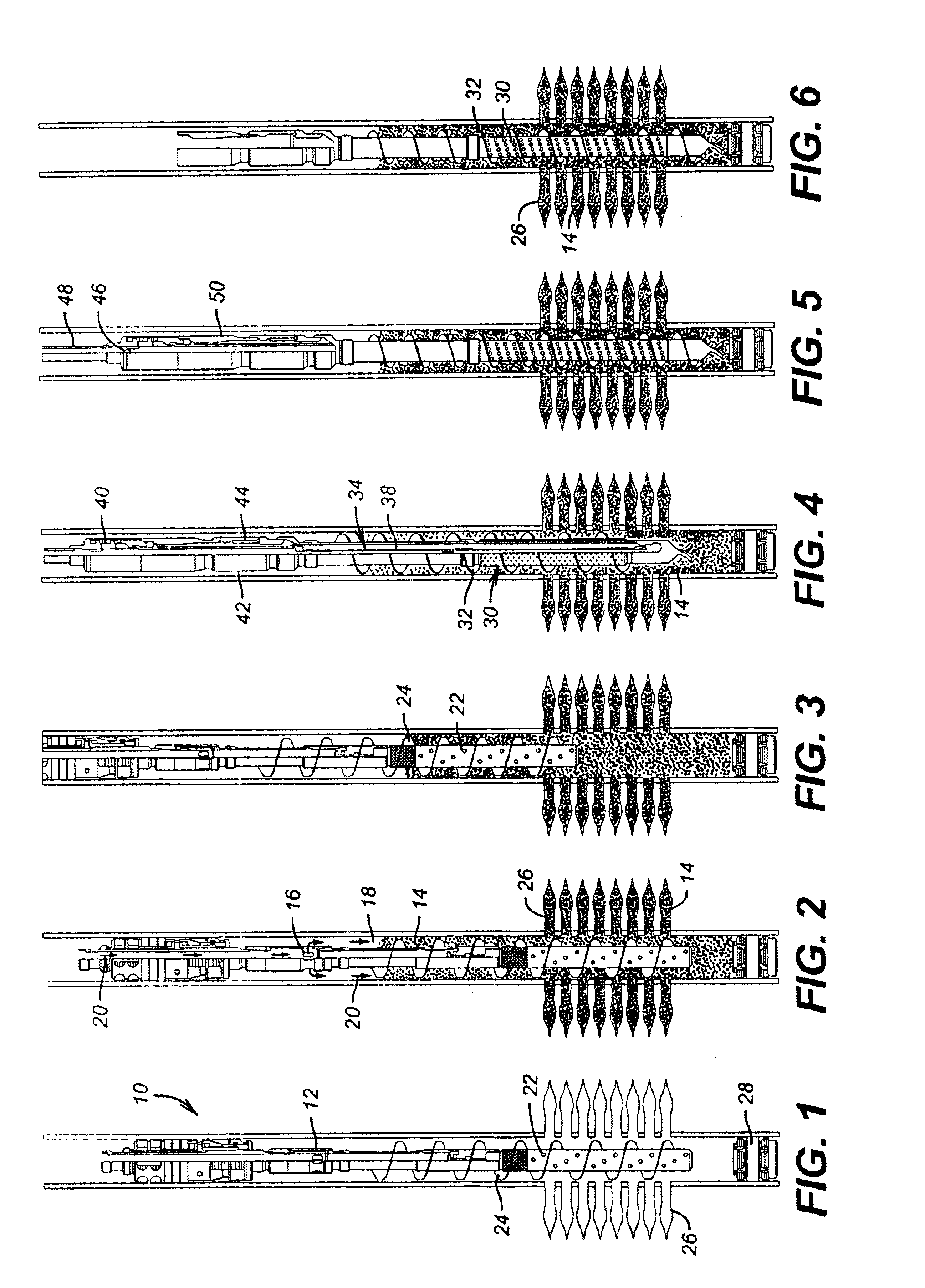
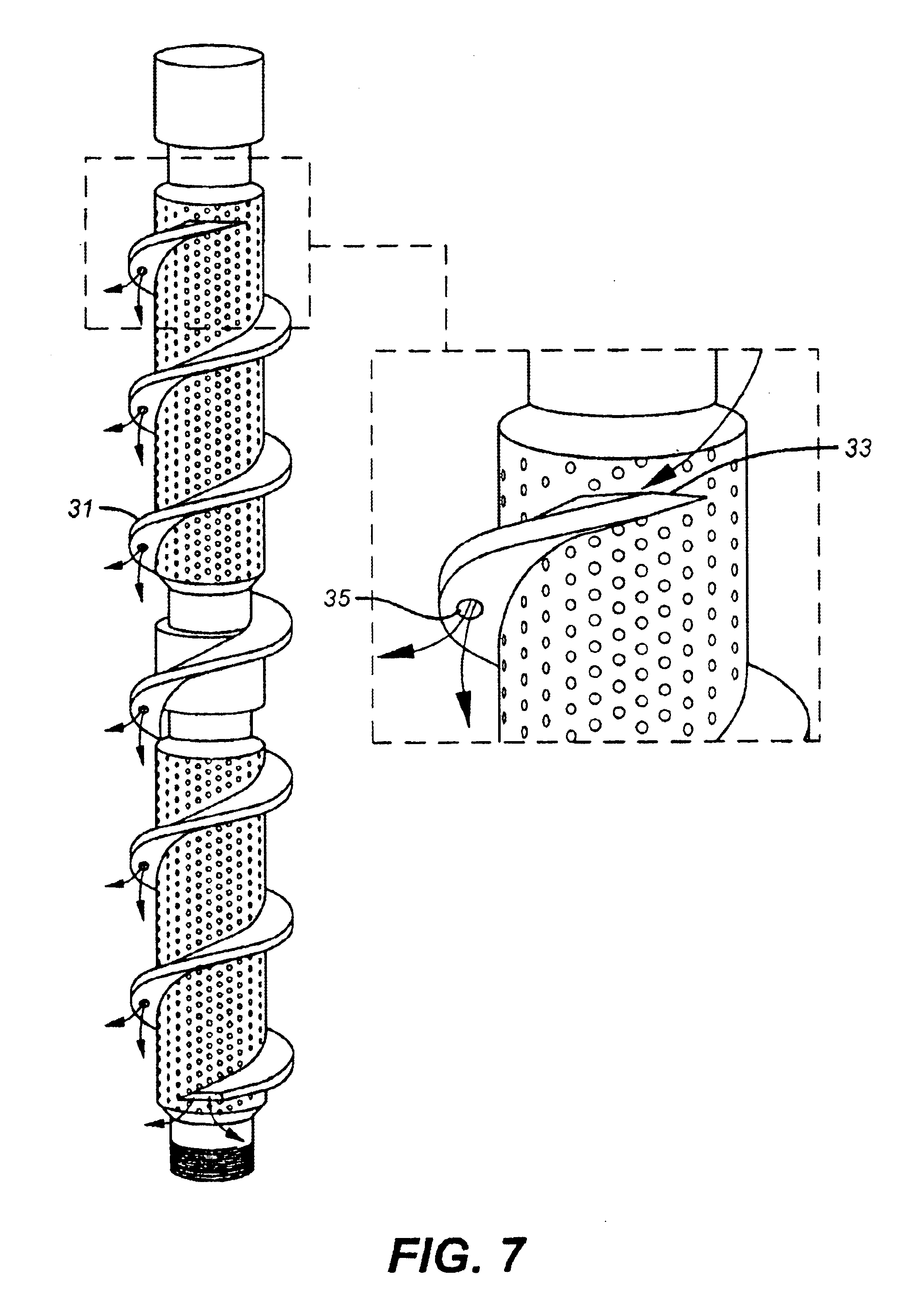
FIG. 1 illustrates an isolation packer 10 delivered on a tubing string (not shown). Below the packer is a crossover 12 that permits gravel 14 to exit ports 16 to enter annulus 18 as shown in FIG. 2. Arrows 20 represent the flow of gravel and fracturing fluid into annulus 18, which occurs after the gun 22, is in the desired position shown in FIG. 1. Gun 22 has an exterior auger 24 to facilitate its extraction after being shot and creating perforations 26. An isolation packer 28 may be set below the perforating gun 22.
FIG. 2 shows the gravel 14 forced into the perforations 26 as part of the fracturing process initiated from the surface with the introduction of pressurized fluid and the gravel 14. Fracturing begins after well fluids are first reversed out. As a result of the fracturing, the gravel 14 is forced into the perforations 26 to hold them open and promote production. The gravel 14 also reduces sand production from the formation. At the end of the fracturing operation when the ...
PUM
 Abstract
Description
Claims
Application Information
 - R&D
- Intellectual Property
- Life Sciences
- Materials
- Tech Scout
- Unparalleled Data Quality
- Higher Quality Content
- 60% Fewer Hallucinations
Browse by: Latest US Patents, China's latest patents, Technical Efficacy Thesaurus, Application Domain, Technology Topic, Popular Technical Reports.
© 2025 PatSnap. All rights reserved.Legal|Privacy policy|Modern Slavery Act Transparency Statement|Sitemap|About US| Contact US: help@patsnap.com


