By-pass valve mechanism and method of use hereof

a technology of bypass valve and valve body, which is applied in the direction of fluid removal, borehole/well accessories, sealing/packing, etc., can solve the problems of inability to carry out normal operation, and inability to prevent the flow of fluid, so as to reduce the effect of pressure surge, improve the transfer of fluid, and speed up the run rate

Inactive Publication Date: 2006-10-03
SCHLUMBERGER TECH CORP
View PDF4 Cites 12 Cited by
  • Summary
  • Abstract
  • Description
  • Claims
  • Application Information

AI Technical Summary

Benefits of technology

[0010]It is also a feature of the present invention to provide a novel by-pass valve mechanism that incorporates a test pressure control system and permits pressure testing of a well without causing pressure responsive closure of the sliding sleeve valve mechanism thereof.
[0011]It is an even further feature of the present invention to provide a novel by-pass valve mechanism that is closed responsive to hydrostatic pressure or pump pressure within a well and which achieves locking of the sliding sleeve valve element at its closed position to prevent inadvertent opening thereof responsive to treatment fluid injection pressure or formation pressure.
[0012]Briefly, a by-pass valve mechanism embodying the principles of the present invention comprises a unique closable sliding sleeve by-pass valve that is designed for connection with a well service tool to provide an alternate flow path for displaced well bore fluids to travel across flow sensitive or restrictive bottom hole assemblies. The additional flow path minimizes pressure surges and the thus minimizes the potential for prematurely energizing cup type seals while running the tool assembly into a well casing. The tool may also be used to minimize fluid loss and to minimize the potential for related well control problems.
[0014]The present invention employs a unique, ported sliding sleeve mechanism (by-pass valve) as an alternate flow path to improve the transfer of fluids across sensitive or restrictive tool assemblies. The alternate flow path is created by channeling fluid through the tool ID to the annulus between the well casing and the by-pass valve via by-pass ports that are defined by the valve body of the by-pass valve mechanism. The by-pass valve is designed with a substantially non-restricted flow path to reduce the effect of pressure surges and to allow faster run in rates of the well service tool. Decreasing pressure surges and flow along the tool exterior will also minimize wear of service tool and by-pass valve components and minimize the risk of the premature setting of flow and pressure sensitive sealing elements.
[0015]The by-pass valve mechanism is unique in that it is composed of a compact closable sliding sleeve which may set to close automatically at a predetermined depth, in response to hydrostatic pressure, or manually closed at a predetermined pump in pressure. Once closed the by-pass valve isolates the fluid supplying and tool conveyance tubing from the annulus between the well casing and the by-pass valve and provides a near smooth ID for high treatment fluid flow rate applications. Hydraulic areas are designed into internal by-pass valve components to maintain the valve mechanism tightly closed in response to applied tubing pressure.
[0016]The by pass valve is primarily intended to be used with cup type sealing devices such as CoilFRAC™ tools but may also be used with compression type sealing element devices. The by-pass valve may also be used with non-pressure sensitive tools to minimize formation damage from pressure surges and to minimize the fluid loss that is normally associated with the running in of tools on either coiled tubing or jointed pipe.

Problems solved by technology

Bull-heading, i.e., displacing well fluid into a reservoir, is often unacceptable as it can lead to well control problems, cause formation damage and can induce pressure surges that are intolerable by some flow or pressure sensitive devices.
However, in some applications the tubing may be intentionally blocked, or the device may utilize cup type or flow sensitive sealing elements which may prevent displaced fluid flow externally of the tool.
Tools using cup type self energizing sealing elements are very sensitive to differential pressure or flow and may become prematurely energized if the tool run in speed exceeds the by-pass capabilities.
Similar mechanical devices may have been used with coiled tubing, however, the inventors are not aware of the existence of any automatic, hydraulic type actuated valve used with coiled tubing for the purpose of relieving pressure sensitive devices or formations.
Electronic / hydraulic, pressure operated valves such as the IRIS™ have also been used for similar jointed pipe applications; however, they are very complicated, expensive and, due to their relatively large OD (greater than 4″) and long length, it is unlikely that such a valve could be feasibly applied to coiled tubing applications.

Method used


Image

  • By-pass valve mechanism and method of use hereof
  • By-pass valve mechanism and method of use hereof
  • By-pass valve mechanism and method of use hereof

Examples


Embodiment Construction

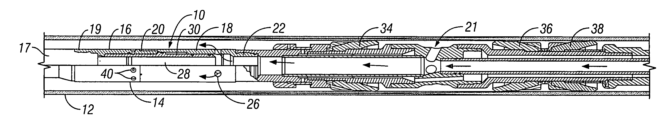
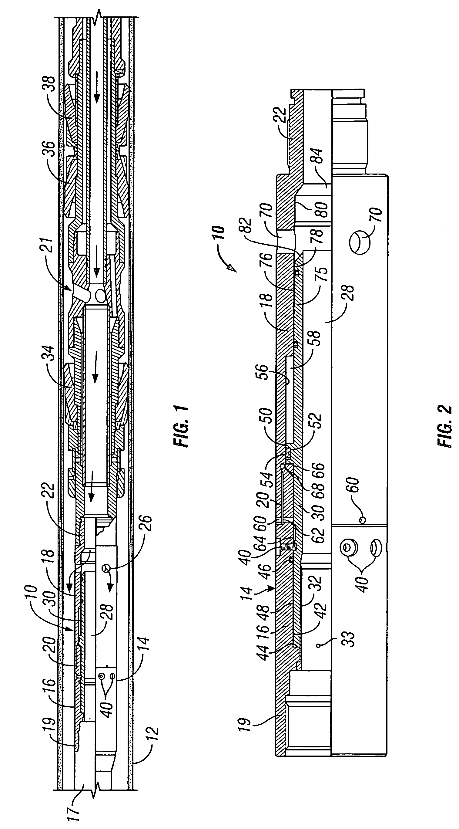
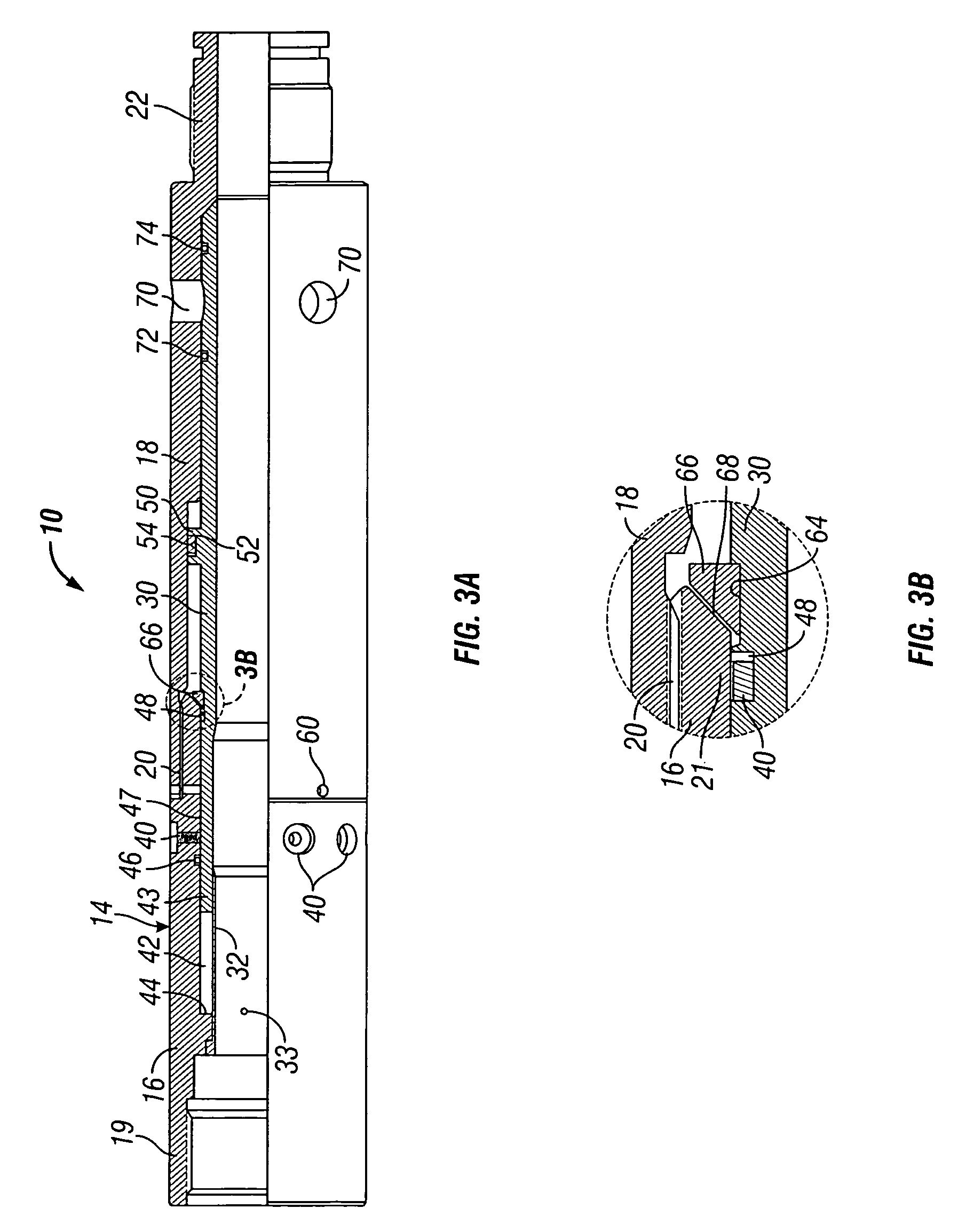
[0027]Referring now to the drawings and first to FIG. 1, a by-pass valve mechanism or assembly embodying the principles of the present invention is shown generally at 10 and is shown to be located within a well casing 12, such as during its conveyance downwardly through the well casing to a depth or location of interest. The by-pass valve, as illustrated in FIG. 1, is composed of a fixed outer ported housing shown generally at 14 and having upper and lower housing sections 16 and 18, being connected in assembly by an intermediate connection 20. A tubing connector 17 of a conveyance and fluid supplying tubing string is received by a connector 19 defined by the upper end of the upper housing section 14, thus providing for connection of the by-pass valve assembly with the tubing string for fluid supply to a well service tool shown generally at 21 and for conveyance of the well service tool within the well casing.

[0028]The lower housing section 18 defines a tool connection 22 to provide...


PUM


Abstract

A by-pass valve mechanism for a well treatment tool having at least one flow sensitive element, permitting by-pass of well fluid past the flow sensitive element of the well treatment tool during conveyance of the well treatment tool to treatment depth within a well. A valve housing adapted for connection with a well tool defines an internal flow passage and has at least one by-pass port communicating well fluid between the flow passage of the service tool and the annulus between the well casing and the service tool. A sliding sleeve valve element is normally secured at its open position by shear elements permitting flow of well fluid through the and is moveable between an open position diverting fluid flow from within the service tool to the annulus and a closed position blocking the flow of well fluid through the by-pass port. The sleeve valve element is released and automatically closed by predetermined hydrostatic tubing or casing pressure or pump pressure. The by-pass valve mechanism may have a test pressure control system permitting pressure testing of a well without causing release and closure of the sleeve valve.

Description

RELATED PATENT APPLICATION[0001]Applicants hereby claim the benefit of U.S. Provisional Application Ser. No. 60 / 448,334 filed on Feb. 19, 2003 and entitled “By-pass Valve & Method”, which provisional application is incorporated herein by reference for all purposes.BACKGROUND OF THE INVENTION[0002]1. Field of the Invention[0003]The present invention relates generally to by-pass valves to provide for by-pass of fluid within a well casing past a well tool having packer elements as the tool is being run into a well to provide a well servicing activity. More particularly, the present invention concerns a by-pass valve having a unique closable sleeve valve that provides an alternative flow path for displaced well fluids to travel across flow sensitive or restrictive bottom hole assemblies.[0004]2. Description of the Prior Art[0005]The process of conveying tools into well bores filled with fluid generally involves a displacement of fluids. During conveyance of a well tool within a well, fl...

Claims


Application Information

Patent Timeline
Patent Type & Authority Patents(United States)
IPC IPC(8): E21B23/06E21B33/12E21B33/129
CPCE21B33/1294
Inventor BISSONNETTE, H. STEVENRYDER, KEITH A.MCKEE, L. MICHAEL
Owner SCHLUMBERGER TECH CORP
Why Eureka
Try Eureka